
Water turbine speed regulator embedded control object model simulation method

A hydraulic turbine model and control object technology, applied in simulators, general control systems, control/regulation systems, etc., can solve problems such as expensive equipment, abnormal frequency channel signals, and complicated test wiring, achieving low cost and improving integrity , strong portability

Inactive Publication Date: 2018-04-27
NANJING NARI GROUP CORP
View PDF3 Cites 14 Cited by
  • Summary
  • Abstract
  • Description
  • Claims
  • Application Information

AI Technical Summary

Problems solved by technology

However, this solution has the disadvantage of expensive equipment. A set of special equipment can easily cost hundreds of thousands, and small power plants or governor manufacturers cannot afford it at all.
The test wiring is relatively complicated. It is necessary to connect the guide vane opening, blade opening, circuit breaker signal, etc. to the simulation device, and connect the simulation output power, frequency and other signals to the governor. The equipment test requires a disassembly and assembly of the cable, which greatly reduces the test efficiency
At present, the quality of the simulation devices on the market is not reliable. There are often problems such as abnormal frequency channel signals, inaccurate analog measurements, and the signal is susceptible to interference due to poor grounding. However, the manufacturers of the simulation devices cannot repair product failures in a timely manner. One of the reasons why the device is widely criticized by power plants

Method used


Image

  • Water turbine speed regulator embedded control object model simulation method
  • Water turbine speed regulator embedded control object model simulation method
  • Water turbine speed regulator embedded control object model simulation method

Examples


Embodiment Construction

[0058] The present invention will be further described below. The following examples are only used to illustrate the technical solution of the present invention more clearly, but not to limit the protection scope of the present invention.

[0059] There are three main simulation methods for general systems: Physical simulation, which uses a reduced or simplified physical model for simulation research. The advantage is simple and intuitive, but there are problems such as relatively fixed system structure and difficult parameter changes; Establishing a mathematical model to simulate the system is more flexible, but many actual physical characteristics cannot be described by a mathematical model, resulting in simulation distortion; hybrid simulation is a test method that combines physical models, mathematical models and real objects, so often A more satisfactory effect can be obtained. The present invention is actually a hybrid simulation method, which combines the water turbine...


PUM


Abstract

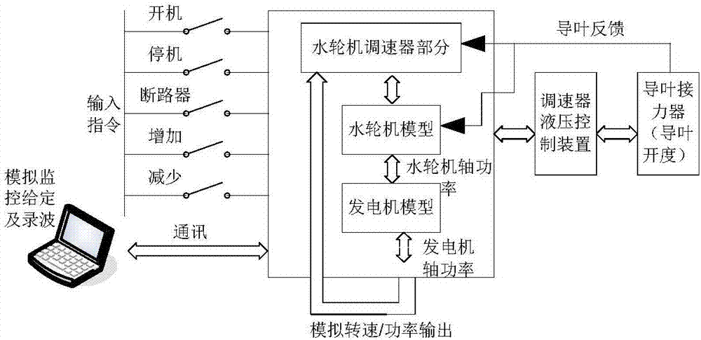
The invention discloses a water turbine speed regulator embedded control object model simulation method. A water turbine model, a generator model and a fault diagnosis module are embedded in a water turbine speed regulator; through acquiring basic parameters of an actual controlled water turbine and a generator set, the water turbine model and the generator model are respectively abstracted into Laplace transfer function expressions; differential discrete transformation of the Laplace transfer function expressions is carried out for program calculation, water turbine guide vane relay feedbackis acquired to input to the water turbine model, output of the water turbine model is inputted to the generator model, the generator rotation speed and the active power output are calculated; the generator rotation speed and an active power signal are fed back to an actual speed regulator cabinet, and rotation speed and power closed loop control on a speed regulation system is realized. The methodis advantaged in that the method is independent from external simulation equipment, the simulation test and fault diagnosis of the speed regulation system can be realized through utilizing self resources of the speed regulator, and factory test integrity of the speed regulator equipment is improved.

Description

technical field [0001] The invention relates to a method for simulating an embedded control object model of a water turbine speed governor, belonging to the technical field of water turbine speed governor control. Background technique [0002] The turbine governor is an important piece of equipment in a hydropower plant. It undertakes the task of adjusting the speed of the turbine and controlling the output. Its performance directly affects the adjustment quality, safety and stability of the unit. Therefore, whether the governor can perform accurately and quickly And functional testing is particularly critical. The governor of a water turbine is in a complex system of water, machine and electricity. In order to test its operating performance, it must be tested in conjunction with the object it is regulated and controlled. Therefore, to test the performance of the governor, it must be released Into the entire hydropower unit system. It is generally realized through a series...

Claims


Application Information

Patent Timeline
IPC IPC(8): G05B17/02
CPCG05B17/02
Inventor 蔡卫江张雷靳光永何林波荣红钱凤秦晓峰梅高鑫
Owner NANJING NARI GROUP CORP
Learn More