
Power supply conversion circuit

A power conversion circuit and resistor technology, which is applied in the direction of circuit devices, emergency protection circuit devices, output power conversion devices, etc., can solve the problems of occupying chip area, large chip area, and occupancy

Active Publication Date: 2018-04-27
SHANGHAI AWINIC TECH CO LTD
View PDF5 Cites 10 Cited by
  • Summary
  • Abstract
  • Description
  • Claims
  • Application Information

AI Technical Summary

Problems solved by technology

[0005] LDO has the advantage of high output voltage accuracy, but it needs to provide a reference voltage on the bandgap reference, and it also involves complex feedback loop compensation. The design complexity is very high, and it will occupy a large chip area.
Based on some analog integrated circuits, the precision requirement of the power supply voltage is not very high, only the power supply voltage is required to be within the safe range, and the internal circuit will not be burned, and the power supply capacity requirement is not very high, usually below the mA level. In some cases, continuing to use LDO will cause an unnecessary increase in cost
[0006] At present, there is no simple and reliable technology that can generate multiple output power supplies. For example, an LDO can only generate one output power supply. If you want to output two-channel power supplies, you need to make two LDOs, which occupies a greater degree of chip area.

Method used


Image

  • Power supply conversion circuit
  • Power supply conversion circuit
  • Power supply conversion circuit

Examples


Embodiment Construction

[0035] The following will clearly and completely describe the technical solutions in the embodiments of the present invention with reference to the accompanying drawings in the embodiments of the present invention. Obviously, the described embodiments are only some, not all, embodiments of the present invention. Based on the embodiments of the present invention, all other embodiments obtained by persons of ordinary skill in the art without making creative efforts belong to the protection scope of the present invention.

[0036] In order to make the above objects, features and advantages of the present invention more comprehensible, the present invention will be further described in detail below in conjunction with the accompanying drawings and specific embodiments.

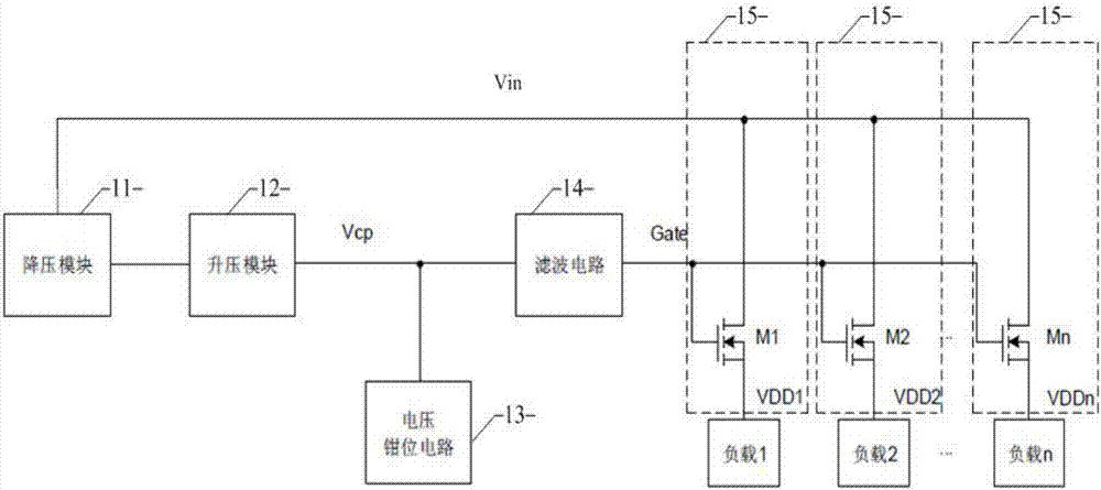
[0037] refer to figure 1 , figure 1 It is a schematic structural diagram of a power conversion circuit provided by an embodiment of the present invention.

[0038] The power conversion circuit includes:

[0039...


PUM


Abstract

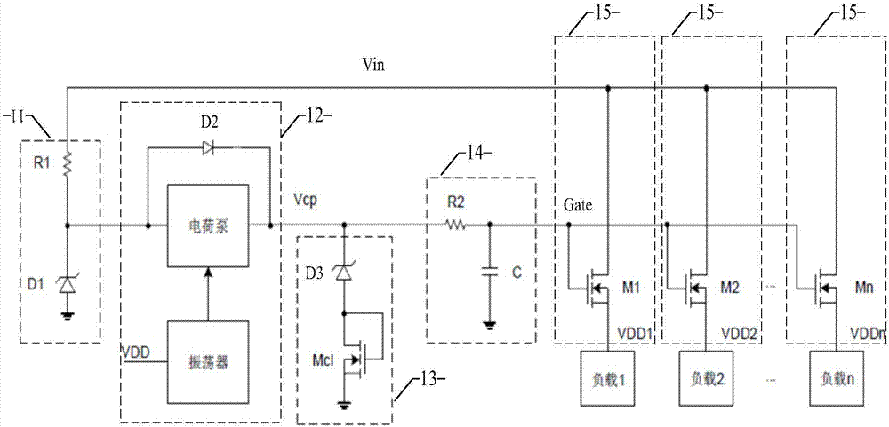
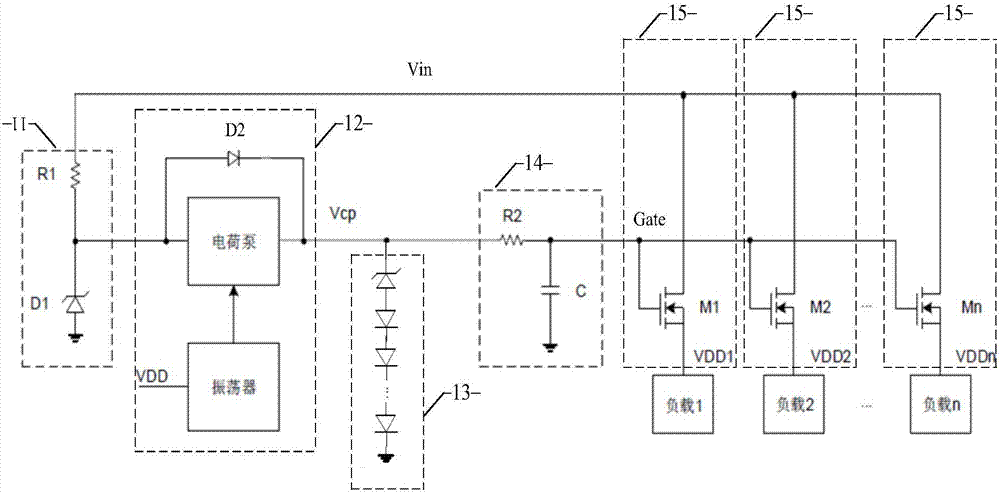
The invention discloses a power supply conversion circuit. The circuit comprises a voltage reduction module, a boost module, a voltage clamping module, a filtering module and at least one output module, wherein the voltage reduction module is used for reducing an input voltage to a preset low voltage value; the boost module is used for increasing the input voltage or the preset low voltage value to a target voltage; the voltage clamping module is used for maintaining the target voltage in a preset voltage range; the filtering module is used for filtering a ripple wave in the target voltage; and the output module is used for providing power for a load. Compared with an LDO circuit in the prior art, the power supply conversion circuit can be used to realize multipath output power supply. When one path of output power supply is increased, only one field effect transistor needs to be increased. The circuit structure is simple and is easy to expand. And the circuit is suitable for a simulation integration circuit which needs multiple paths of power supplies.

Description

technical field [0001] The present invention relates to the technical field of power conversion circuits for integrated circuits, and more specifically, to a power conversion circuit. Background technique [0002] With the continuous development of science and technology, various electronic devices have been widely used in people's daily life and work, bringing great convenience to people's life and work. [0003] Based on the analog integrated circuit, when the input voltage range is large, a power conversion module is generally required to convert the wide-range input voltage into a lower constant voltage to supply power to the internal circuit. [0004] The traditional power conversion method is to integrate an LDO (Low Dropout Regulator, low-voltage linear regulator) inside the chip. The LDO uses a transistor operating in the linear region to subtract the excess voltage from the applied input voltage to generate a regulated The output voltage. [0005] LDO has the adva...

Claims


Application Information

Patent Timeline
IPC IPC(8): H02M3/156
CPCH02M3/156H02M1/008H02M1/14H02M3/07G05F3/18G05F3/185H02H9/041G05F3/24H02M1/0045H02M1/0064G05F1/577H02M1/009
Inventor 罗旭程胡建伟程剑涛
Owner SHANGHAI AWINIC TECH CO LTD
Learn More