A kind of DC offset elimination circuit and method

A technology for DC offset and circuit elimination, applied in electrical components, transmission systems, etc., can solve problems such as power consumption, large storage space, consumption, etc., to achieve the effect of improving speed

Active Publication Date: 2020-04-17
NATIONZ TECH INC
View PDF9 Cites 0 Cited by
  • Summary
  • Abstract
  • Description
  • Claims
  • Application Information

AI Technical Summary

Problems solved by technology

For the continuous calibration method, the continuous operation of the circuit will cause continuous power consumption, which is not conducive to low power design
For the pre-calibration method, the output DC offset voltage of the receiver is related to the IF gain, so this method needs to be calibrated separately under different gains, and a look-up table is established to store the calibration results under different gains. In this way, on the one hand The required calibration time is long, which will affect the establishment speed of the receiver. On the other hand, it requires a large storage space, which will consume a large chip area, which is not conducive to reducing costs and improving integration
[0004] From the above analysis, it can be seen that several traditional DC offset calibration methods are difficult to meet the requirements of zero-IF receivers for low power consumption, high integration and low cost at the same time

Method used


Image

  • A kind of DC offset elimination circuit and method
  • A kind of DC offset elimination circuit and method
  • A kind of DC offset elimination circuit and method

Examples


Embodiment Construction

[0046] The principles and features of the present invention are described below in conjunction with the accompanying drawings, and the examples given are only used to explain the present invention, and are not intended to limit the scope of the present invention.

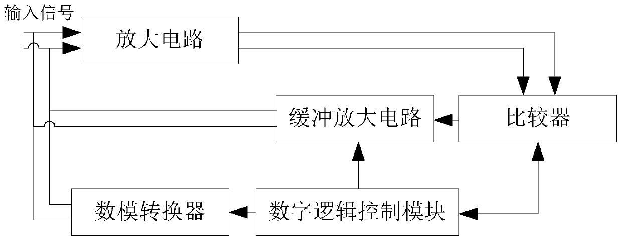
[0047] Such as figure 1 As shown, a DC offset elimination circuit includes: an amplifier circuit, a comparator, a digital logic control module, a digital-to-analog converter and a buffer amplifier circuit.

[0048] The two input terminals of the amplifying circuit are respectively connected to two input signals for amplifying the voltages of the two input signals and outputting two differential signals.

[0049] The two input terminals of the comparator are respectively connected to the two output terminals of the amplifying circuit for comparing the two differential signals and obtaining corresponding digital signals according to the comparison results.

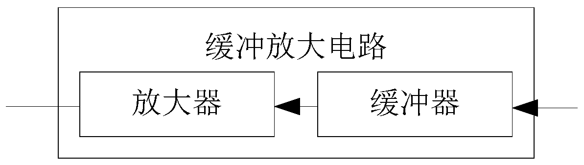
[0050] The input end of the buffer amplifier circuit is con...


PUM


Abstract

The invention relates to a direct current offset elimination circuit, comprising an amplifier circuit, a comparer, a digital logic control module, a digital to analog converter and a buffer amplifiercircuit. After two ways of input signals are amplified by the amplifier circuit and are compared by the comparer, one way is processed by the buffer amplifier circuit, then is input into the amplifiercircuit and is used for increasing voltage difference of the input signals of the amplifier circuit. The other way is processed by the digital logic control module, thereby acquiring a control bit for adjusting the digital to analog converter. The digital to analog converter carries out digital to analog conversion on the control bit of the digital logic control module and then calibrates the twoways of input signals of the amplifier circuits, thereby eliminating direct current offset voltages of the two ways of input signals. According to the circuit and the method, the direct current voltage offset occurring in radio frequency signals can be eliminated, and the direct current offset elimination speed is improved.

Description

technical field [0001] The invention relates to the field of wireless communication, in particular to a DC offset elimination circuit and method. Background technique [0002] Among common wireless receiver structures, low-IF receivers have great advantages in low power consumption and high integration, and are widely used in today's wireless devices. However, since the IF signal of the low-IF receiver is located near the baseband, it is easy to cause the DC operating point of the receiver link to shift or even saturate after being amplified step by step, so the DC offset cancellation technology is very critical in the design of the low-IF receiver. [0003] The traditional DC offset cancellation methods currently used in low-IF receivers are generally divided into two categories: analog cancellation methods and digital-analog hybrid calibration methods. The traditional analog elimination method is equivalent to a high-pass filter in terms of amplitude-frequency response, f...

Claims


Application Information

Patent Timeline
Patent Type & Authority Patents(China)
IPC IPC(8): H04B1/10
CPCH04B1/1027
Inventor 张存才赵辉
Owner NATIONZ TECH INC
Why Eureka
Try Eureka