
Cutter handle with shock absorption function

A tool handle and cutting tool technology, which is applied in the direction of manufacturing tools, stone processing tools, stone processing equipment, etc., can solve the problems of severe vibration of coated tools and coating shedding, etc., achieve smooth processing surface, improve processing precision, and reduce defects effect of influence

Pending Publication Date: 2018-05-01
SHENYANG JIANZHU UNIVERSITY
View PDF1 Cites 3 Cited by
  • Summary
  • Abstract
  • Description
  • Claims
  • Application Information

AI Technical Summary

Problems solved by technology

This method is difficult to fix the chuck part of the milling cutter. Due to the high-speed rotation of the spindle, the damping particles in the tool holder may also be eccentric, which will make the coated tool vibrate more violently and the coating will fall off.

Method used


Image

  • Cutter handle with shock absorption function
  • Cutter handle with shock absorption function
  • Cutter handle with shock absorption function

Examples


Embodiment 1

[0037] In this embodiment, the coated ball-end milling cutter works in the milling range of stone: the spindle speed is 2000-8000r / min; the feed rate is 500-3000mm / min; the cutting depth is 0.5-2mm;

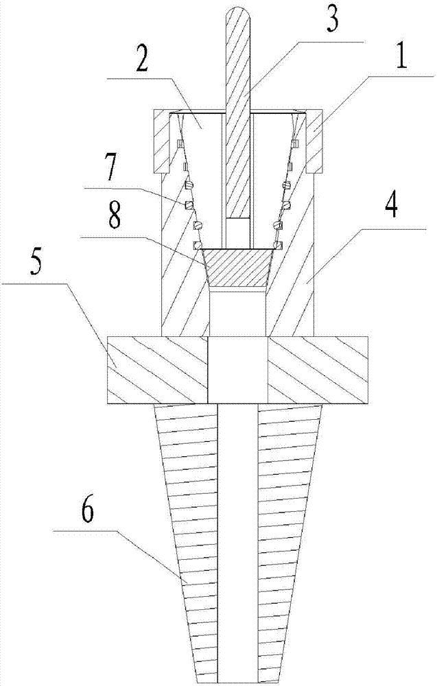
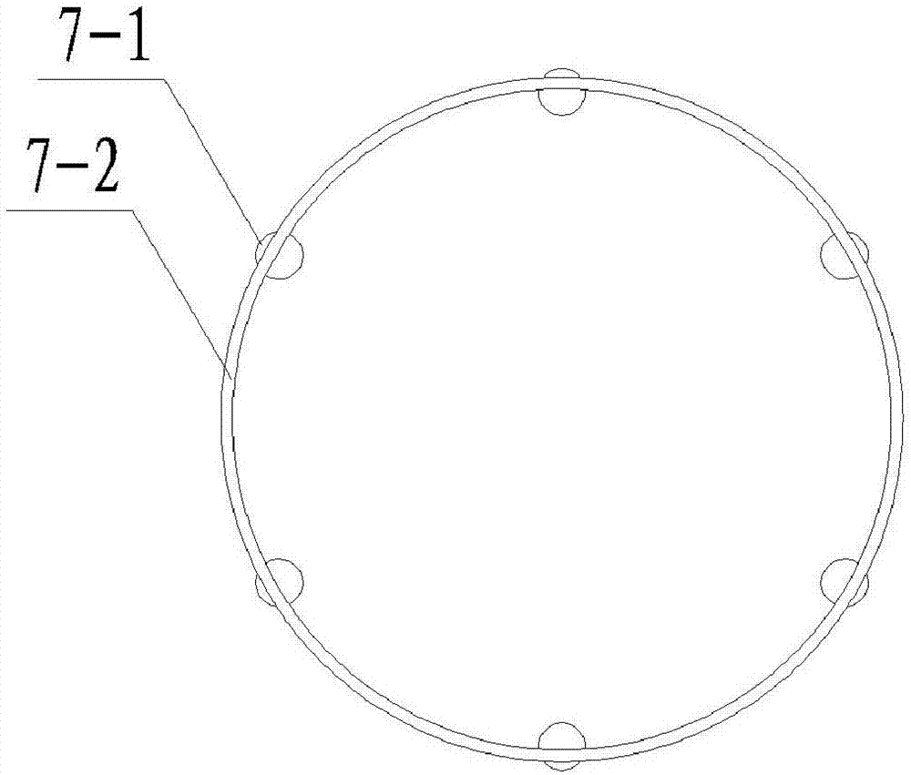
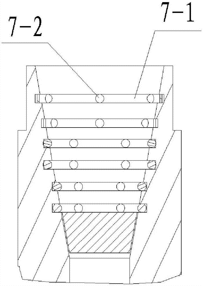
[0038] A coated ball end milling cutter holder with vibration damping function, its cross-sectional view is as follows figure 1 As shown, the structural diagram of the shock absorbing device of the tool holder is shown in figure 2 As shown, the local schematic diagram of the shock absorber is shown in image 3 As shown, it includes a handle body 4, a damping block 8 and a collet 2. The lower part of the handle body 4 is provided with a handle seat 5 and a handle portion 6 in sequence. The collet 2 is a carbon steel spring collet, and the coating The length-to-diameter ratio (L / D) of the ball end milling cutter is 4 to 6, L is the length of the milling cutter, D is the diameter of the milling cutter, where:

[0039] The handle body 4 is provided with an inner hole, and the inne...


PUM

PropertyMeasurementUnit
particle diameteraaaaaaaaaa
ultimate tensile strengthaaaaaaaaaa
impact strengthaaaaaaaaaa

Abstract

The invention relates to a cutter handle with a shock absorption function. The cutter handle with the shock absorption function comprises a handle body, a damping block and a clamping head, wherein aninner hole is formed in the handle body and used for holding the damping block and the clamping head. The damping block is arranged at the bottom of the inner hole. The clamping head is arranged on the upper portion of the damping block. Four to six circles of grooves are formed in the surface of the inner hole. Shock absorption devices are arranged in the grooves and surround the periphery of the clamping head. The cutter handle with the shock absorption function is simple in structure, and convenient to use. When stone is machined, shaking or vibration of the surface of the stone is reduced. The damping block and the shock absorption devices convert kinetic energy into potential energy, the vibration amplitude of the milling cutter clamping head is relieved, vibration of a milling cutter is further relieved, and the surface coating of the milling cutter is protected. The machining accuracy of the surface of the stone is improved, and the service life of the coated cutter can also beprolonged.

Description

Technical field: [0001] The invention belongs to the technical field of coated cutting tools, and in particular relates to a cutting tool holder with vibration damping function. Background technique: [0002] The vibration of the machine tool in the process of milling stone is very complicated. There are many reasons for the vibration, mainly: because the internal structure of the stone is not uniform and is a hard and brittle material, a large enough external force may be generated during milling. Moreover, the frequency of the external excitation force is the same as the natural frequency of the process system and then resonates; the shape of the stone is complex and diverse, and the selection of the clamping position when processing the stone is unreasonable; the selection of parameters such as cutting amount and machine speed is unreasonable; it may also be some forced Vibration, such as the foundation of the machine tool, the gap of the screw of the machine tool, the da...

Claims


Application Information

Patent Timeline
Patent Type & Authority Applications(China)
IPC IPC(8): B28D1/18
CPCB28D1/186
Inventor 陆峰王筱晴查丽琼闫广宇吴玉厚
Owner SHENYANG JIANZHU UNIVERSITY
Learn More