
Printing and dyeing equipment

A technology of printing and dyeing equipment and dyeing box, which is applied in the directions of drying fabrics, equipment configuration for processing textile materials, printing, etc., can solve problems such as affecting the quality of textiles, reducing production efficiency, increasing production costs, etc., to improve dyeing effect and quality. , the effect of improving work efficiency

Active Publication Date: 2018-05-01
TONGXIANG LONGXIANG PRINTING & DYEING CO LTD
View PDF5 Cites 20 Cited by
  • Summary
  • Abstract
  • Description
  • Claims
  • Application Information

AI Technical Summary

Problems solved by technology

[0005] In the prior art, the textiles printed and dyed by the printing and dyeing device contain a large amount of water, so it is necessary to use dehydration equipment to separate the printing and dyeing wastewater contained in the textiles, while the traditional dehydration method mostly uses centrifugal dehydration, and most of the textiles after centrifugal dehydration are due to centrifugal force. The role of the fabric is reversed and becomes rope-like, and wrinkles will also occur on the textile, which affects the quality of the textile. At the same time, after dehydration, it needs to be widened and shaped on the open-width machine, which adds a step process and increases the production cost. In addition, the traditional dyeing machine It only has the effect of dyeing, and the function is relatively single. In the printing and dyeing process of textiles, the printing and dyeing equipment, dehydration equipment and printing equipment are all independent equipment. During production, the equipment needs to be replaced to continue working, which reduces the production efficiency.

Method used


Image

  • Printing and dyeing equipment
  • Printing and dyeing equipment
  • Printing and dyeing equipment

Examples


Embodiment Construction

[0033] The following will clearly and completely describe the technical solutions in the embodiments of the present invention with reference to the accompanying drawings in the embodiments of the present invention. Obviously, the described embodiments are only some, not all, embodiments of the present invention. Based on the embodiments of the present invention, all other embodiments obtained by persons of ordinary skill in the art without making creative efforts belong to the protection scope of the present invention.

[0034] see Figure 1-7 , the present invention provides a technical solution:

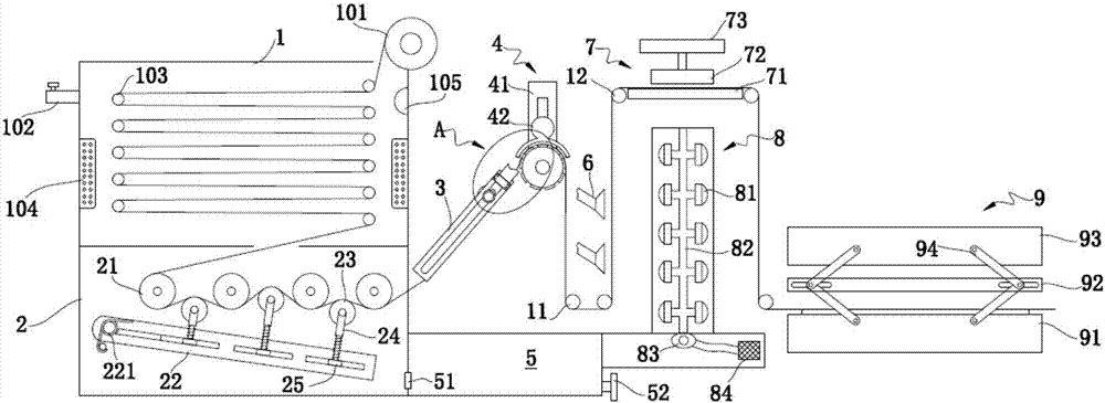
[0035] A printing and dyeing equipment, including a dyeing box, a dehydration drying mechanism and a printing machine 9 arranged in sequence from left to right.

[0036] The dyeing box includes a first dyeing box 1 and a second dyeing box 2. The upper end of the first dyeing box 1 is provided with an unwinding roller 101, and a plurality of transfer rollers 103 are interlaced insi...


PUM


Abstract

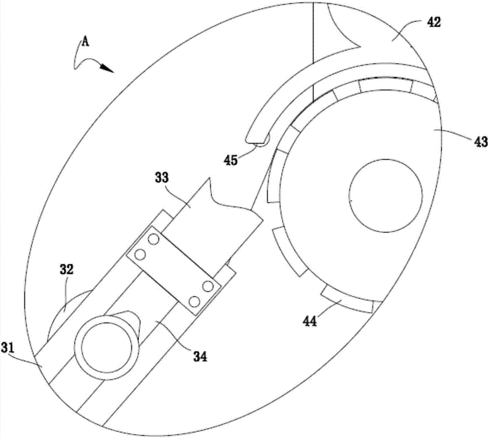
The invention provides printing and dyeing equipment. The printing and dyeing equipment comprises a dyeing box, a dewatering and drying mechanism and a printing machine which are arranged from left toright sequentially. The dewatering and drying mechanism comprises a dewatering mechanism, a water absorbing mechanism, an ironing mechanism and a drying machine which are arranged from left to rightsequentially. The dewatering mechanism comprises a guide rail frame. A water pressing roller is mounted in a groove of the guide rail frame movably through a wheel. An air cylinder is arranged on theright side of the guide rail frame. A piston rod of the air cylinder is connected with the water pressing roller. The water absorbing mechanism comprises a water pressing plate and a water absorbing roller. The printing and dyeing equipment has the advantages that centrifugal dewatering is not needed after textile dyeing through the dewatering and drying mechanism, so that flattening degree of textiles is guaranteed, and flattening on a scutcher is not needed; the dyeing equipment, the dewatering and drying equipment and the printing equipment are combined, so that equipment replacement time during working is reduced, dyeing and printing can be completed on one equipment, and working efficiency is improved.

Description

technical field [0001] The invention relates to the technical field of textile equipment, in particular to a printing and dyeing equipment. Background technique [0002] Printing and dyeing, also known as dyeing and finishing, is a processing method and a general term for pretreatment, dyeing, printing, finishing, washing, etc. [0003] For example, a dye tank for textile processing provided by Chinese Patent Publication No. "CN107164902A" includes a main body, a motor-driven device and a movable guide roller. Both sides of the upper end surface of the main body are fixedly equipped with reinforcing plates. The upper end surface of the plate is rotatably connected with a first yarn guide roller, and the symmetrical position of the first yarn guide roller relative to the main body is rotatably connected with a second yarn guide roller, and the motor drive device is fixedly installed between the first yarn guide roller and the Between the second yarn guide rollers, both the f...

Claims


Application Information

Patent Timeline
IPC IPC(8): D06B3/12D06B3/34D06B1/02D06B15/00D06B15/02D06B15/04D06B23/20D06B23/22B41F17/00
CPCB41F17/003D06B1/02D06B3/12D06B3/345D06B15/00D06B15/02D06B15/043D06B23/20D06B23/22D06C2700/09
Inventor 朱世新
Owner TONGXIANG LONGXIANG PRINTING & DYEING CO LTD
Learn More