A tidal current power generation cast-in-place pile with a pile core steel pipe and its construction method

A technology of tidal current power generation and construction method, which is applied to sheet pile walls, foundation structure engineering, construction, etc., can solve the problems of high cost of large-diameter cast-in-situ pile engineering, influence on tidal current energy utilization, and inability to bear loads, etc., and achieve simple construction procedures, The effect of pile foundation structure optimization and casting quality improvement

Active Publication Date: 2019-12-10
ZHEJIANG PROVINCIAL INST OF COMM PLANNING DESIGN & RES CO LTD
View PDF5 Cites 0 Cited by
  • Summary
  • Abstract
  • Description
  • Claims
  • Application Information

AI Technical Summary

Problems solved by technology

[0007] In order to solve the problem that the existing conventional diameter cast-in-situ piles cannot bear the load generated by the high-velocity tidal current, the large-diameter cast-in-place piles occupy too much effective tidal current passing section, thereby affecting the utilization of tidal current energy, and at the same time, the project cost of large-diameter cast-in-place piles is too high , the present invention provides a pouring pile for tidal current power generation with pile core steel pipe and its construction method

Method used


Image

  • A tidal current power generation cast-in-place pile with a pile core steel pipe and its construction method
  • A tidal current power generation cast-in-place pile with a pile core steel pipe and its construction method
  • A tidal current power generation cast-in-place pile with a pile core steel pipe and its construction method

Examples


Embodiment Construction

[0034]In order to describe the present invention more specifically, the technical solution of the present invention and its construction process will be described in detail below in conjunction with the accompanying drawings and specific embodiments.

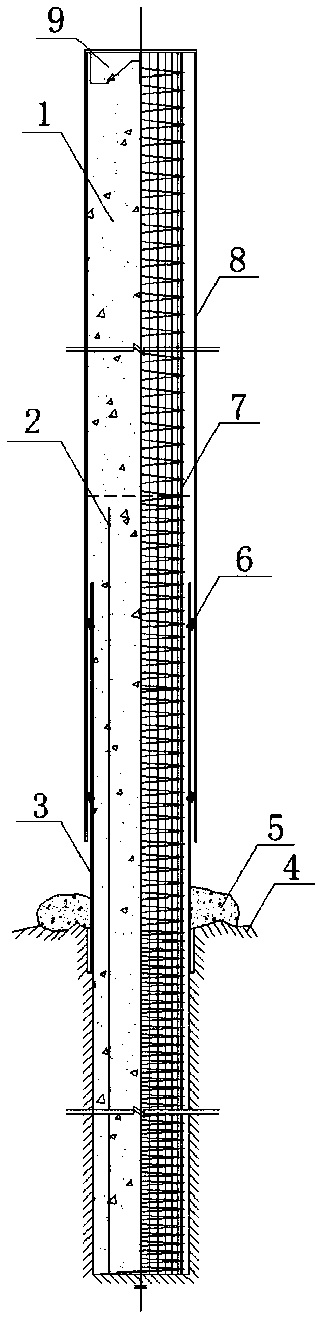
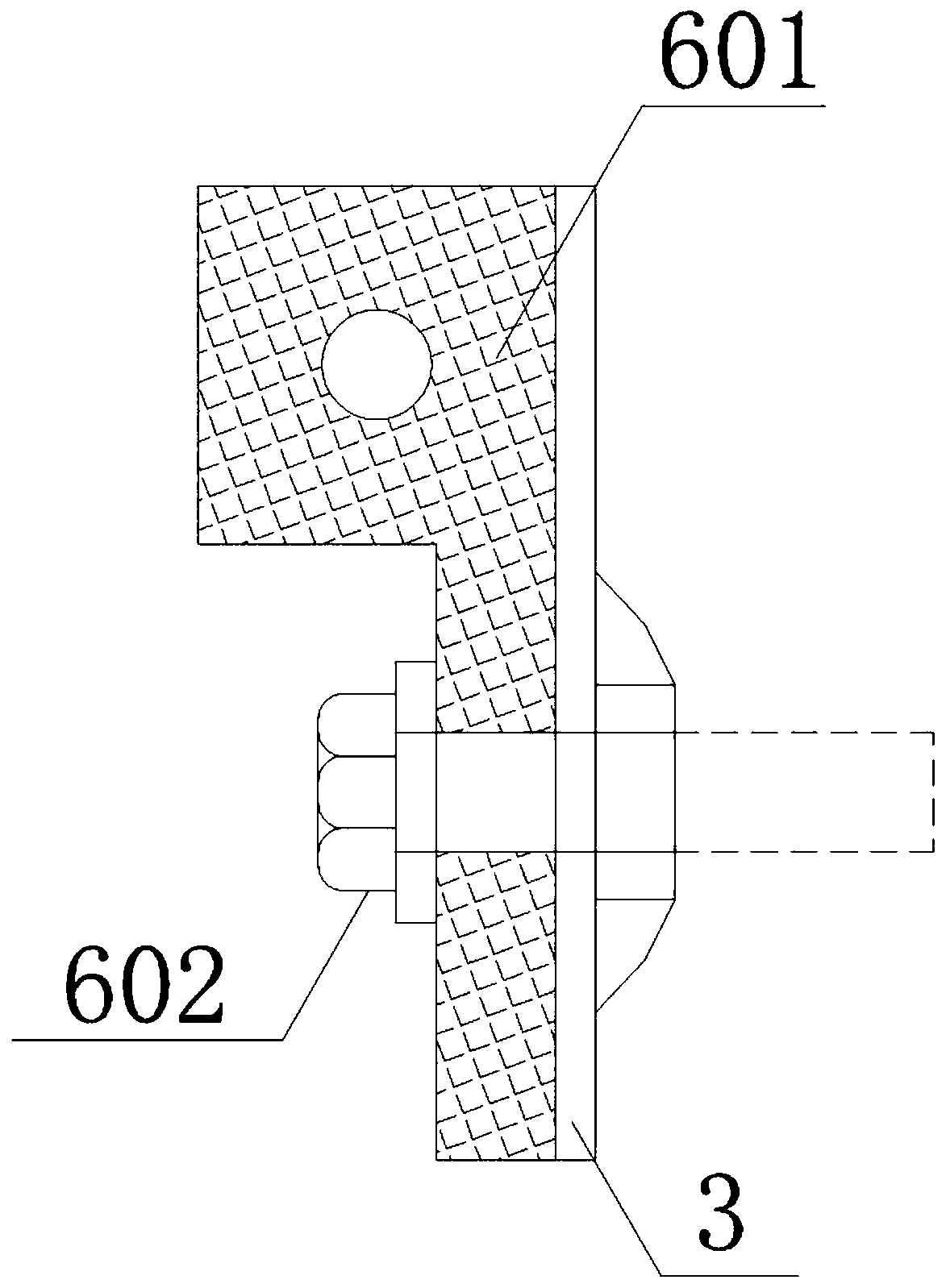
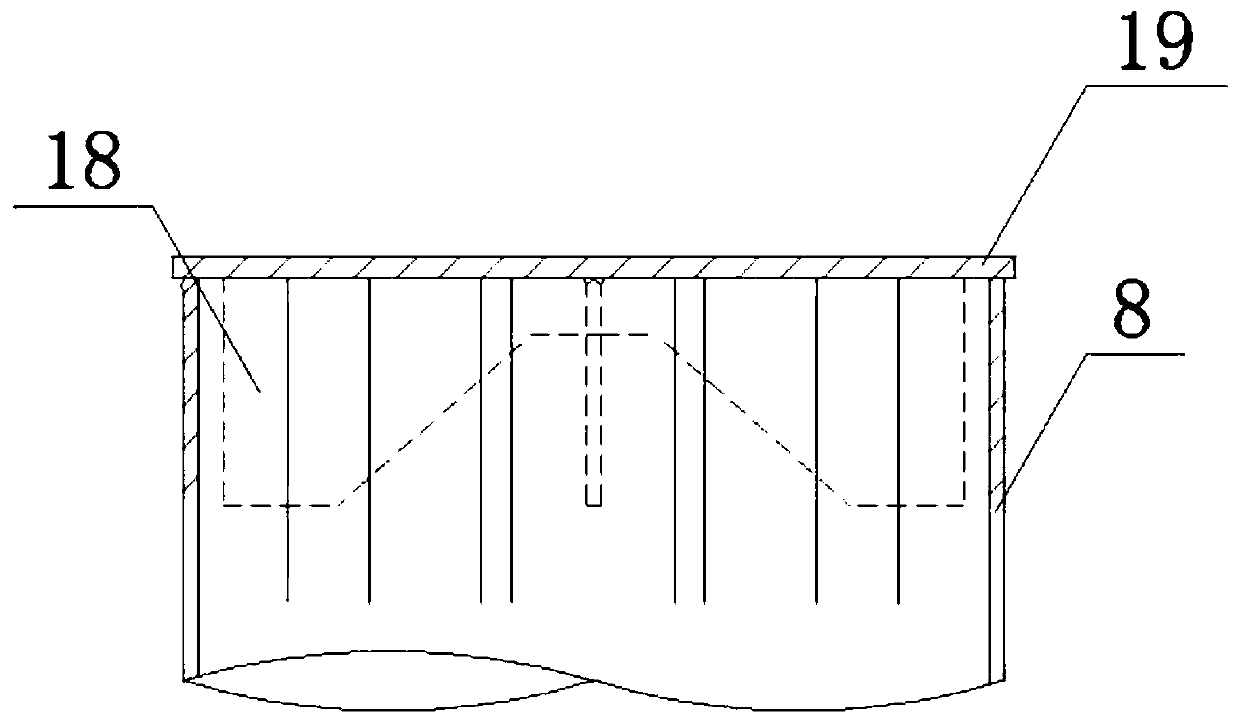
[0035] Such as figure 1 As shown, the tidal current power generation cast-in-situ pile 1 with a pile core steel pipe of the present invention includes a connecting sleeve 3, an outer sleeve 8, a reinforcement cage 7, a capping steel plate 9 and a pile core steel pipe 2, and the outer sleeve 8 is connected to the outer frame of the assembly platform In one piece, the outer sleeve 8 is provided with a reinforcement cage 7, the top of the outer sleeve 8 is welded to the capping steel plate 9, the lower part of the outer sleeve 8 is overlapped with the connecting sleeve 3 through the water-stop rubber 6, and the connecting sleeve 3 is embedded in the In the seabed bedrock layer 4, the cast-in-place pile 1 is poured from the embedded...


PUM


Abstract

The invention discloses a tidal flow electricity generation cast-in-place pile provided with a pile core steel pipe, and a construction method of the tidal flow electricity generation cast-in-place pile. The cast-in-place pile has the advantages of relatively small diameter, high bending and shear resistance and simple and convenient construction procedures; the cast-in-place pile also solves theproblems that an existing common-diameter cast-in-place pile cannot bear overlarge load generated by a large tidal flow speed in a tidal-flow-energy-rich region and a large-diameter cast-in-place pileoccupies too much of an effective tidal flow cross section, so utilization of tidal flow energy is affected and the construction cost of the large-diameter cast-in-place pile is too high. According to the tidal flow electricity generation cast-in-place pile disclosed by the invention, a pile core steel pipe with a certain length is hit into a rock-socketed cast-in-place pile with a common diameter; a pile foundation of the cast-in-place pile is ensured to be embedded in a depth which is 6 m below a seabed bed rock layer; under the reciprocating load effects of wave, tidal flow and the like, and especially under an extreme weather condition, the pile core steel pipe and a steel reinforcement cage can together play relatively high bending resistance and shear resistance of the cast-in-placepile; so the cast-in-place pile is especially applicable to an offshore area engineering foundation such as the foundation of a tidal flow electricity generation pile which bears a relatively large horizontal load, is high in flexibility and has relatively good economic benefits and social benefits.

Description

technical field [0001] The invention belongs to the technical field of offshore pile foundation engineering, and in particular relates to a pouring pile for tidal current power generation with a pile core steel pipe and a construction method thereof. Background technique [0002] Under the action of the gravitational force of celestial bodies, seawater produces periodic motion, and the flow in the horizontal direction is called tidal current. Tidal currents exist in the entire ocean, and the tidal current velocity in the open ocean is very small, but under the influence of factors such as land and seabed topography, strong tidal currents exist in coastal waters, especially between straits and submarine waterways. [0003] The method of developing tidal current energy at sea is mainly based on the combination of tidal current energy generating units and supporting carriers. There are two types of supporting carriers: floating and fixed. The floating carrier is fixed on the s...

Claims


Application Information

Patent Timeline
Patent Type & Authority Patents(China)
IPC IPC(8): E02D5/38E02D15/04
CPCE02D5/38E02D15/04
Inventor 何晓宇沈坚应永良金国强季大闰
Owner ZHEJIANG PROVINCIAL INST OF COMM PLANNING DESIGN & RES CO LTD
Why Eureka
Try Eureka