Non-orthogonal correction method for workpiece stage and correction device

A calibration method and technology of a calibration device, applied in the field of lithography, can solve the problems of inability to meet the requirements of the whole machine, long calibration time, far less than the frequency of mirror changes, etc.

Active Publication Date: 2018-05-01
SHANGHAI MICRO ELECTRONICS EQUIP (GRP) CO LTD
View PDF6 Cites 0 Cited by
  • Summary
  • Abstract
  • Description
  • Claims
  • Application Information

AI Technical Summary

Problems solved by technology

Ideally, when the workpiece table moves along the Y direction, there will be no crosstalk to the X direction, but in order to ensure that when the workpiece table moves along the Y direction, the measured value in the X direction will not change, that is, the optical path will not change. When there is a surface shape, in order to ensure that the optical path remains unchanged, the workpiece table needs to move in the X direction to compensate for the impact. At this time, the workpiece table measurement coordinate system is not an ideal coordinate system, but a curved coordinate system, which cannot meet the needs of the whole machine
In order to make the coordinate system of the workpiece table an ideal coordinate system, we need to periodically calibrate the mirror surface shape, but if the processing material of the mirror is affected by heat and changes seriously, when mass production, the off-line calibration frequency is far less than the mirror change frequency, so it is necessary to Measure its impact online
The existing calibration methods for high-order mirror surfaces are usually realized by using a stepping motion workpiece table, that is, the workpiece table needs to stop during the test. The disadvantage of this is that the calibration time is long and the efficiency is low.

Method used


Image

  • Non-orthogonal correction method for workpiece stage and correction device
  • Non-orthogonal correction method for workpiece stage and correction device
  • Non-orthogonal correction method for workpiece stage and correction device

Examples


Embodiment Construction

[0034] The present invention is described in detail below in conjunction with accompanying drawing:

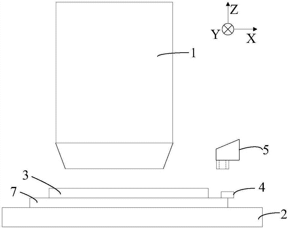
[0035] Such as Figure 2-4 As shown, the present invention provides a non-orthogonal correction method for a workpiece table, comprising the following steps:

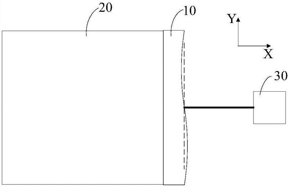
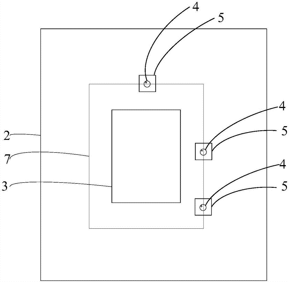
[0036] S1: Set non-orthogonal measurement marks 6 on the coarse motion rotary table 7 used to carry the substrate 3 on the workpiece table 2. The non-orthogonal measurement marks 6 are provided with at least three, and are not on a straight line, so as to measure the workpiece table. 2 for on-line measurement, in this embodiment, three reflectors 4 are set on the coarse motion rotating table 7, and the three non-orthogonal measurement marks 6 are set on the three said non-orthogonal measurement marks 6 one by one On the reflecting mirror 4, there are three visual units 5 correspondingly.

[0037] S2: select three non-orthogonal measurement marks 6, move the workpiece table 2, and align the vision unit 5 with the three...


PUM


Abstract

The invention discloses a non-orthogonal correction method for a workpiece stage and a correction device. The correction device comprises non-orthogonal measurement marks, which are arranged on a coarse-movement turn table on the workpiece stage, wherein the coarse-movement turn table is used for bearing a base plate, and at least three measurement marks are arranged and are not located on a samestraight line; visual units, which are used for acquiring the positions of the non-orthogonal measurement marks; an interferometer measuring unit, which is used for measuring the position of the workpiece stage; and a correction unit, which calculates the non-orthogonal amount of the workpiece stage according to the nominal positions of the non-orthogonal measurement marks in a coordinate system of the turn table, the positions of the non-orthogonal measurement marks acquired by the visual units and the position of the workpiece stage, and transmitting the non-orthogonal amount to the interferometer measuring unit for compensation and correction. The correction method and correction device provided by the invention effectively prevent TP control precision from the influence of the surfacedeformation of the workpiece stage due to heat in the process of exposure, so the usage cost of materials is reduced.

Description

technical field [0001] The invention relates to the technical field of photolithography, in particular to a non-orthogonal correction method and a correction device for a workpiece table. Background technique [0002] The projection scanning TFT (Thin Film Transistor, thin film transistor) lithography machine is used to clearly and correctly image the pattern on the mask on the substrate coated with photoresist. As the size of the substrate increases, a larger flat mirror needs to be used As the measuring mirror of the workpiece stage interferometer, the surface shape change of the square mirror has become the main factor restricting the accuracy of TP (Total Pitch). [0003] When the mirror surface changes little, usually offline periodic calibration is enough, but when the surface shape is greatly deformed by heat, the offline calibration cycle can no longer meet the needs. In addition, the change of the rotation attitude of the mirror will also affect the non-orthogonali...

Claims


Application Information

Patent Timeline
Patent Type & Authority Applications(China)
IPC IPC(8): G03F7/20
CPCG03F7/70716G03F7/7085Y02P90/02
Inventor 马琳琳杨志勇孙刚朱健朱树存
Owner SHANGHAI MICRO ELECTRONICS EQUIP (GRP) CO LTD
Why Eureka
Try Eureka