Jet flow radiating equipment

A technology of heat dissipation equipment and jet flow, which is applied to the structural parts of electrical equipment, cooling/ventilation/heating transformation, electrical components, etc., and can solve the problems of large space occupied by cooling equipment, low working reliability, and low cooling performance.

Inactive Publication Date: 2018-05-01
YUNAN JINGCHUANG LIQUID METAL THERMAL CONTROL TECH RES & DEV CO LTD
View PDF4 Cites 0 Cited by
  • Summary
  • Abstract
  • Description
  • Claims
  • Application Information

AI Technical Summary

Problems solved by technology

However, the cooling equipment of the current electronic system occupies a large space, has low cooling performance, cannot adapt to airborne conditions, and has low reliability

Method used


Image

  • Jet flow radiating equipment
  • Jet flow radiating equipment

Examples


Embodiment Construction

[0022] The specific implementation manners of the present invention will be further described in detail below in conjunction with the accompanying drawings and embodiments. The following examples are used to illustrate the present invention, but are not intended to limit the scope of the present invention.

[0023] In the description of the present invention, it should be noted that unless otherwise specified, the meaning of "plurality" is two or more; the terms "upper", "lower", "left", "right", "inner ", "outside", "front end", "rear end", "head", "tail", etc. indicate the orientation or positional relationship based on the orientation or positional relationship shown in the drawings, and are only for the convenience of describing the present invention and Simplified descriptions, rather than indicating or implying that the device or element referred to must have a particular orientation, be constructed and operate in a particular orientation, and thus should not be construe...


PUM


Abstract

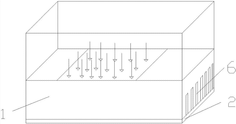
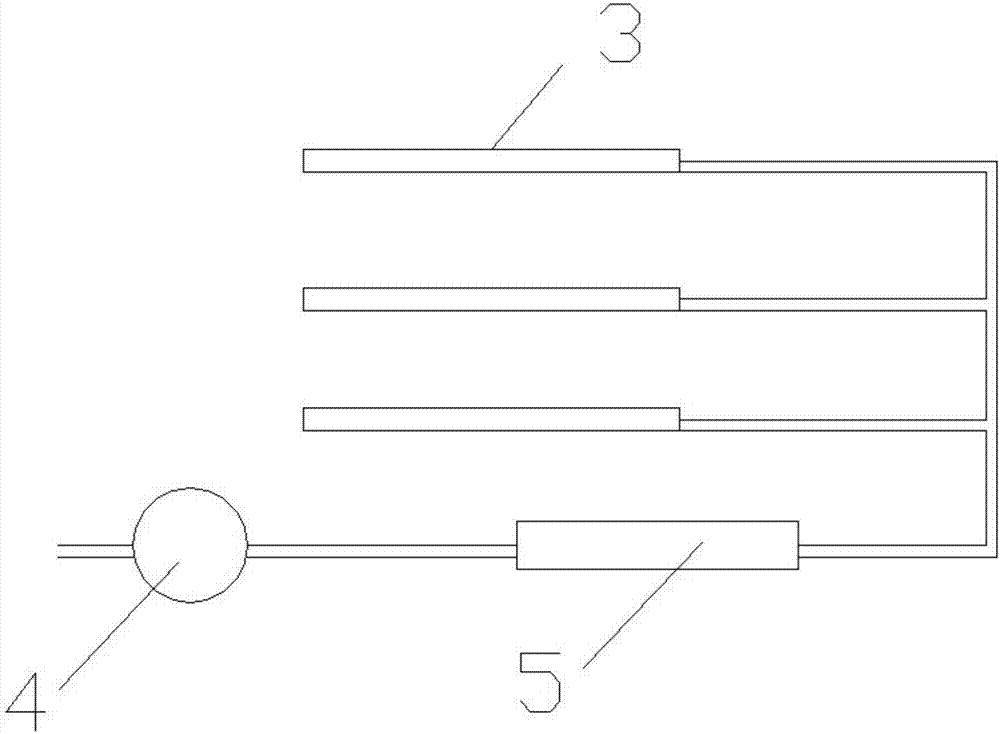
The invention provides jet flow radiating equipment, and the equipment comprises a radiator body and a control unit. The radiator body is of a cavity structure. The bottom plate of the cavity is connected with an element; The interior of the cavity is provided with a getter pump, a heat exchanger, and a spraying assembly. The getter pump, the heat exchanger and the spraying assembly are connectedsequentially, and an air inlet of the getter pump is communicated with the cavity. The spraying assembly is used for spraying low-melting-point liquid metal towards the bottom plate of the cavity, soas to cool the bottom plate of the cavity. The getter pump is used for recycling the gaseous low-melting-point liquid metal in the cavity. The heat exchanger is used for cooling the low-melting-pointliquid metal. The getter pump, the heat exchanger and the spraying assembly are electrically connected with the control unit. On the one hand, the low-melting-point liquid metal is sprayed on the bottom plate of the cavity, thereby achieving the jet flow cooling and enabling the radiating effect to be good; on the other hand, the low-melting-point liquid metal is vaporized after being heated, thereby dissipating heat and enabling the radiating efficiency to be high. In addition, the getter pump recycles the low-melting-point liquid metal in the cavity, and the heat exchanger cools the low-melting-point liquid metal, thereby achieving the recycling.

Description

technical field [0001] The invention relates to the technical field of heat dissipation equipment for components, in particular to a jet heat dissipation equipment. Background technique [0002] With the development of microelectronics technology, high power consumption electronic packaging has been developed into a complete mechanical assembly. At present, a new generation of integrated avionics systems uses a large number of multi-chip components (MCM); in addition, with the development of technology, SOC (system on chip) will also be gradually applied to the field of avionics. In order to make the above-mentioned electronic system adapt to the thermal environment with harsh airborne conditions, it is necessary to provide supporting cooling equipment. At the same time, due to the improvement of the integration level and operating frequency of electronic equipment, the power density of chips is getting higher and higher, and the requirements for the structure and performan...

Claims


Application Information

Patent Timeline
Patent Type & Authority Applications(China)
IPC IPC(8): H05K7/20
CPCH05K7/20345H05K7/20327
Inventor 蒋清林周罗琴盛磊刘静
Owner YUNAN JINGCHUANG LIQUID METAL THERMAL CONTROL TECH RES & DEV CO LTD
Why Eureka
Try Eureka