RTO waste gas treatment device

A waste gas treatment device and exhaust pipe technology, applied in the direction of combustion method, combustion type, incinerator, etc., can solve problems such as RTO equipment and pipeline corrosion, threats to personal safety, catalyst poisoning, etc., to improve environmental performance and safety , the effect of novel structure

Inactive Publication Date: 2018-05-04
YANGZHOU SANZHONG QIMING ENVIRONMENTAL PROTECTIONEQUIP
View PDF0 Cites 1 Cited by
  • Summary
  • Abstract
  • Description
  • Claims
  • Application Information

AI Technical Summary

Problems solved by technology

[0003] The existing RTO incinerator has the following disadvantages: the organic waste gas is heated by natural gas combustion, and the sulfur in natural gas such as H 2 S is a harmful impurity. Its existence will not only cause RTO equipment and pipeline corrosion, catalyst poisoning, but more seriously, it will threaten personal safety. It is one of the environmental pollutants that must be eliminated or controlled. The existing RTO exhaust gas treatment device When natural gas is used for heating, sulfur-free operation cannot be achieved. Sulfur in natural gas enters the RTO and corrodes equipment and pipelines. At the same time, the discharged gas after treatment will cause air pollution; the regenerator in the incinerator can only enter the "regenerator" after cleaning is completed. Although the heat storage body is continuously cleaned by the gas, the heat storage body will still be broken, damaged, burned, and blocked after a period of use, which will affect the heat storage performance of the heat storage body. If these conditions are found, the regenerative furnace will not work properly

Method used


Image

  • RTO waste gas treatment device

Examples


Embodiment Construction

[0011] Below in conjunction with accompanying drawing, the present invention is further described:

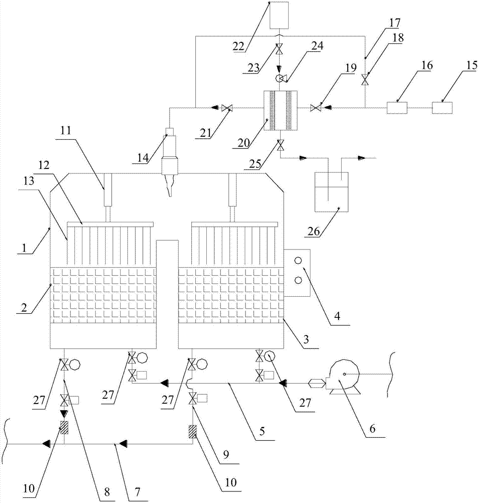
[0012] An RTO exhaust gas treatment device, comprising an incinerator main body 1 and an intake and exhaust pipe connected to the incinerator main body, the incinerator main body 1 includes a regenerative furnace A2, a regenerative furnace B3 and a combustion chamber located above the regenerative furnace , a burner 14 is fixed inside the combustion chamber, a regenerator is arranged inside the regenerative furnace A2 and the regenerative furnace B3, and a fan 6 is arranged on one side of the main body 1 of the incinerator, and the fan 6 is connected to a general Air intake pipe 5, two branch pipes are arranged on the total air intake pipe 5 to connect with the lower ends of the heat storage furnace A2 and the heat storage furnace B3 respectively, the branch pipes are provided with pressure sensors 27 and electric valves, and the heat storage furnace A2 The lower end is also co...


PUM


Abstract

The invention discloses an RTO waste gas treatment device, and belongs to the technical field of environment protection equipment. The RTO waste gas treatment device is novel in structure and reasonable in design. Natural gas obtained after sulfur impurities are moved is adopted as fuel, it is guaranteed that the situation that the sulfur impurities enter an incinerator, and therefore equipment and pipeline corrosion is caused is avoided, and safety of the whole device is improved. The sulfur impurities in the natural gas cannot be discharged into the atmosphere along with treated waste gas, no pollution can be caused to the atmosphere, and the environment protection performance of RTO equipment is improved. Pressure sensors are arranged on a gas inlet and a gas outlet of a heat storage chamber of the incinerator, the gas pressure in the gas inlet pipe and the gas pressure in the gas outlet pipe can be conveniently monitored in real time, and whether the conditions of blocking, breaking and the like happen to a heat storage body in the heat storage chamber or not is judged through whether the gas pressure is within the normal range or not, so that maintenance measures are taken toguarantee normal work of heat storage furnaces. An automatic cleaning tool is arranged on the heat storage body, and the heat storage body can be cleaned periodically.

Description

technical field [0001] The invention relates to the technical field of environmental protection equipment, in particular to an RTO waste gas treatment device. Background technique [0002] RTO is the English abbreviation of regenerative oxidation furnace. Its principle is to oxidize combustible waste gas into corresponding oxides and water at high temperature, thereby purifying the waste gas and recovering the heat released when the waste gas is decomposed. The waste gas decomposition efficiency is higher than that of the traditional one. Direct fired oxidation furnace. RTO generally includes a regenerative type and a combustion chamber. It usually adopts a double regenerative furnace structure. The heat generated in the combustion process is maximized by switching between valves. Each regenerator undergoes heat storage-release-cleaning in sequence. Wait for the program, go round and round, and work continuously. [0003] The existing RTO incinerator has the following disa...

Claims


Application Information

Patent Timeline
IPC IPC(8): F23G7/06
CPCF23G7/066
Inventor 吴智吴承宸
Owner YANGZHOU SANZHONG QIMING ENVIRONMENTAL PROTECTIONEQUIP
Why Eureka
Try Eureka