
Single-pole double-throw switch for radio frequency transceiving switching

A single-pole double-throw switch, radio frequency transceiver technology, applied in electrical components, transmission systems, etc., can solve the problems of large insertion loss, power back-off, and more control voltages for transceivers, reducing insertion loss, reducing size, and simplifying switching. effect of path

Pending Publication Date: 2018-05-04
武汉华讯国蓉科技有限公司
View PDF5 Cites 21 Cited by
  • Summary
  • Abstract
  • Description
  • Claims
  • Application Information

AI Technical Summary

Problems solved by technology

[0004] Purpose of the invention: In order to overcome the problems in the prior art, the present invention proposes a new single-pole double-throw switch for transceiver control of the transceiver link, which can effectively solve the problems of high transceiver control voltage, large insertion loss and high-power signal output process. The power backoff problem that occurs in

Method used


Image

  • Single-pole double-throw switch for radio frequency transceiving switching
  • Single-pole double-throw switch for radio frequency transceiving switching
  • Single-pole double-throw switch for radio frequency transceiving switching

Examples


Embodiment Construction

[0012] The technical solution of the present invention will be further described below in conjunction with the accompanying drawings.

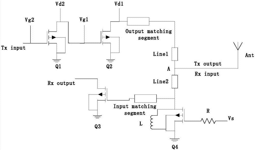
[0013] refer to image 3 , a single-pole double-throw switch for radio frequency transceiver switching includes a first microstrip line Line1, a second microstrip line Line2, and a switch die Q4. One end of the first microstrip line Line1 is connected to the antenna end, and the other end is connected to the output matching end of the transmitting circuit PA; one end of the second microstrip line Line2 is connected to the antenna end, and the other end is simultaneously connected to the LNA input matching end of the receiving circuit and the switch die The drain of Q4 is connected; the source of the switching die Q4 is grounded, and an inductor L is parallelly connected between the drain and the source, and the gate of the switching die Q4 is connected to the control voltage Vs through a resistor R. In addition, in this embodiment, the power ...


PUM


Abstract

The invention belongs to the field of radar antenna control, and provides a single-pole double-throw switch for radio frequency transceiving switching. The switch comprises two microstrip lines and aswitch tube core, wherein one end of a first microstrip line is connected with an antenna, and the other end of the first microstrip line is connected with a PA output matching end; one end of a second microstrip line is connected with the antenna, and the other end of the microstrip line is connected with both an LNA input matching end and a drain of the switch tube core Q4; and a source of the switch tube core Q4 is grounded, an inductor L is connected between the drain and the source in parallel, and a gate is a control end. Compared with the traditional single-pole double-throw switch in which two switch tube cores are connected in parallel and grounded and connection statuses of the two switch tube cores are different, the switch provided by the invention has the advantages that the number of switch transceiving control voltages is reduced, and an original control switch in a transmitting circuit and a 1 / 4 wavelength microstrip line connected with the control switch are removed, so that a switch path is simplified, a transmission route for transmitted signals is shortened, the size is reduced, the problem of transmitting power back-off is effectively avoided, and insertion loss of a transmitting output end is further reduced.

Description

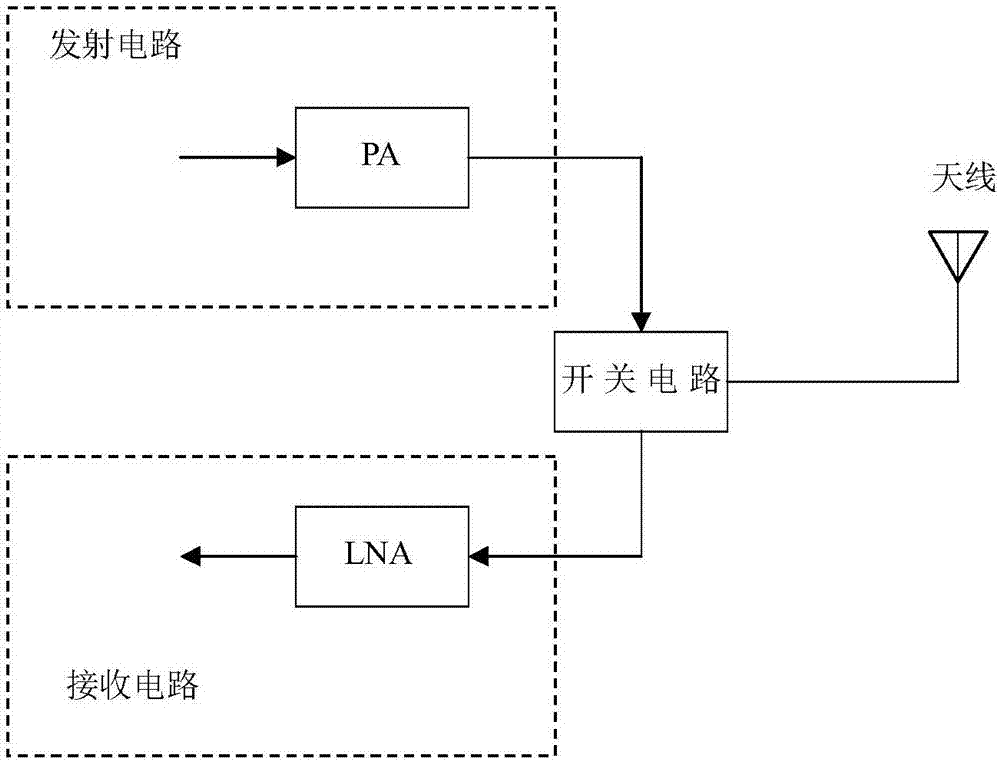
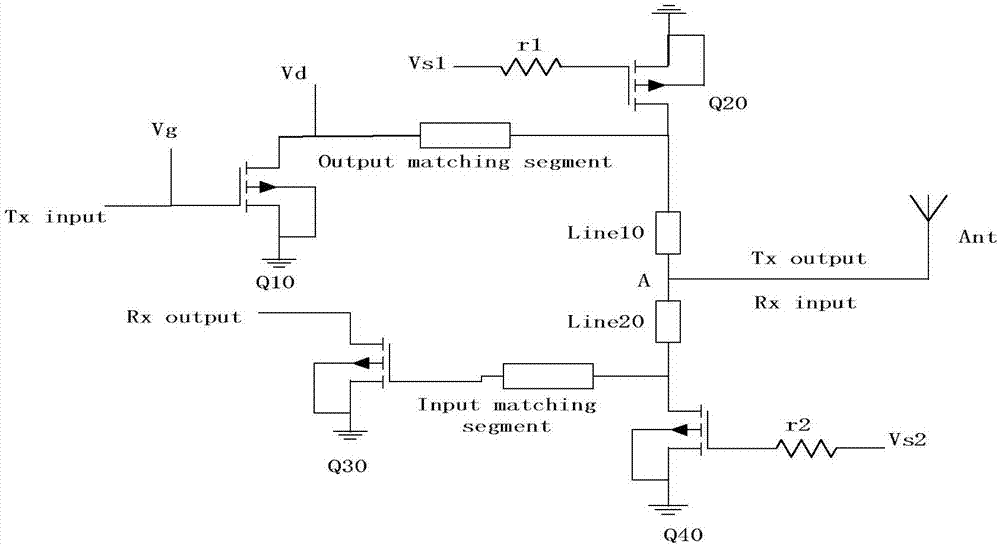
technical field [0001] The invention relates to a radar antenna control circuit, in particular to a single-pole double-throw switch for radio frequency transceiver switching. Background technique [0002] In the radar antenna control circuit, it is necessary to switch and control the sending and receiving circuits. figure 1 The basic structure of the radar antenna circuit is shown. The power amplifier (PA) is used in the transmission path to increase the signal power and then transmitted from the antenna. The low noise amplifier (LNA) is used in the reception path to obtain the signal from the antenna and amplify it to the subsequent processing device. , the switching of the transceiver link is realized by a switch circuit, and the switch circuit mostly adopts a traditional single-pole double-throw switch. [0003] Although the traditional single-pole double-throw switch is simple in principle, it has a larger structure, more switch receiving and sending control voltage, an...

Claims


Application Information

Patent Timeline
Patent Type & Authority Applications(China)
IPC IPC(8): H04B1/44
CPCH04B1/44
Inventor 廖红梅朱贤能
Owner 武汉华讯国蓉科技有限公司
Learn More