Supercharge Your Innovation With Domain-Expert AI Agents!

An ultrasonic beam forming method and system based on sound velocity adaptive correction

A technology of beam synthesis and synthesis method, which is applied in ultrasonic/sonic/infrasonic diagnosis, ultrasonic/sonic/infrasonic image/data processing, acoustic diagnosis, etc. It can solve the problems of affecting imaging quality, low iteration density, time-consuming, etc. Achieve high image resolution, strong contrast, and improve focus quality

Active Publication Date: 2021-01-12
SASET CHENGDU TECH LTD
View PDF10 Cites 0 Cited by
  • Summary
  • Abstract
  • Description
  • Claims
  • Application Information

AI Technical Summary

Problems solved by technology

This method needs to use multiple scans with different sound velocities to obtain multiple RF signals or images corresponding to different sound velocities, which is not only very time-consuming, but also prone to motion errors caused by too long scanning time (heart scan is the most prominent, due to heart motion, multi-frame The difference between the images is large), which makes the optimization time of sound velocity longer and the accuracy of the optimization result is lower
On the other hand, due to the need to use different iterative sound velocities for multiple launches, limited by the probe element scanning switching delay and imaging time requirements, the iterative density of sample sound velocities in this scheme is usually small, and when saving the channel data corresponding to multiple launches Due to the noise caused by motion errors, the accuracy of the obtained sound velocity optimization results cannot meet higher requirements, thus affecting the imaging quality

Method used


Image

  • An ultrasonic beam forming method and system based on sound velocity adaptive correction
  • An ultrasonic beam forming method and system based on sound velocity adaptive correction
  • An ultrasonic beam forming method and system based on sound velocity adaptive correction

Examples


Embodiment Construction

[0041]The following describes the present invention in further detail with reference to the accompanying drawings and embodiments, so as to make the objectives, technical solutions and advantages of the present invention clearer. It should be understood that the specific embodiments described here are only used to explain the present invention, but not to limit the present invention.

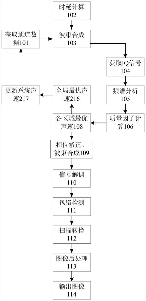
[0042]figure 1 A flowchart of an ultrasonic beam synthesis method based on adaptive correction of sound velocity according to an embodiment of the present invention is shown. Some or all of the steps included in the following steps can be executed individually or in parallel. The step numbers are only used to identify the steps, and are not used to limit the execution order and / or times of the steps.

[0043]Step 101: Use a preset system sound velocity to perform an ultrasonic transmission, and obtain the first channel data according to the echo signals received by each channel

[0044]Among them, the preset s...


PUM


Abstract

The invention discloses a sound velocity self-adaption correction-based ultrasound beam forming method and system, can realize sound velocity optimization self-adaption correction, improve accuracy for a sound velocity optimization result and an optimization result, and provide phase compensation for channel data via optimal sound velocity and improve ultrasound imaging quality. The method comprises steps of conducting ultrasound emission via preset system sound velocity, acquiring first channel data according to an echo signal received by each channel, acquiring sound velocity optimization quality factors of each local area to a plurality of sample sound velocity, for each local area, designating sample sound velocity corresponding to the maximum sound velocity optimization quality as theoptimal sound velocity of the local area, conducting phase correction and beam forming for the first channel data according to a difference between the optimal sound velocity of each local area and the system sound velocity, and then orderly conducting signal demodulation, envelope detection, scan conversion and image post-processing to produce a frame of image.

Description

Technical field[0001]The invention relates to the technical field of ultrasonic imaging, in particular to an ultrasonic beam synthesis method and system based on adaptive correction of sound velocity.Background technique[0002]In the medical ultrasound imaging system, from the ultrasound probe to the final display of the image, it has to go through the transmitting and receiving circuit, analog signal to digital signal conversion, beam synthesis, signal baseband processing, digital scan converter and image post-processing. Among them, the beam synthesis quality of the ultrasound imaging system has a crucial influence on the final imaging effect. The main processing methods of beamforming for channel data include traditional hardware beamforming and software beamforming that has emerged with the development of general-purpose processor capabilities. The related technologies include electronic focus and scan line control, apodization, and aperture change. Whether it is hardware or soft...

Claims


Application Information

Patent Timeline
Patent Type & Authority Patents(China)
IPC IPC(8): A61B8/00
CPCA61B8/52A61B8/5207A61B8/5269
Inventor 石丹刘西耀刘东权
Owner SASET CHENGDU TECH LTD
Features
  • R&D
  • Intellectual Property
  • Life Sciences
  • Materials
  • Tech Scout
  • Unparalleled Data Quality
  • Higher Quality Content
  • 60% Fewer Hallucinations
Learn More