
Small hole punching mechanism

A punching and punching technology, which is applied in the field of small hole punching mechanism, can solve the problems of high frequency of punch replacement, secondary positioning error, and increase of processing cost, and achieve short replacement time, long service life and save processing cost Effect

Inactive Publication Date: 2018-05-08
SUZHOU XINJIESHUN HARDWARE ELECTROMECHANICAL
View PDF0 Cites 0 Cited by
  • Summary
  • Abstract
  • Description
  • Claims
  • Application Information

AI Technical Summary

Problems solved by technology

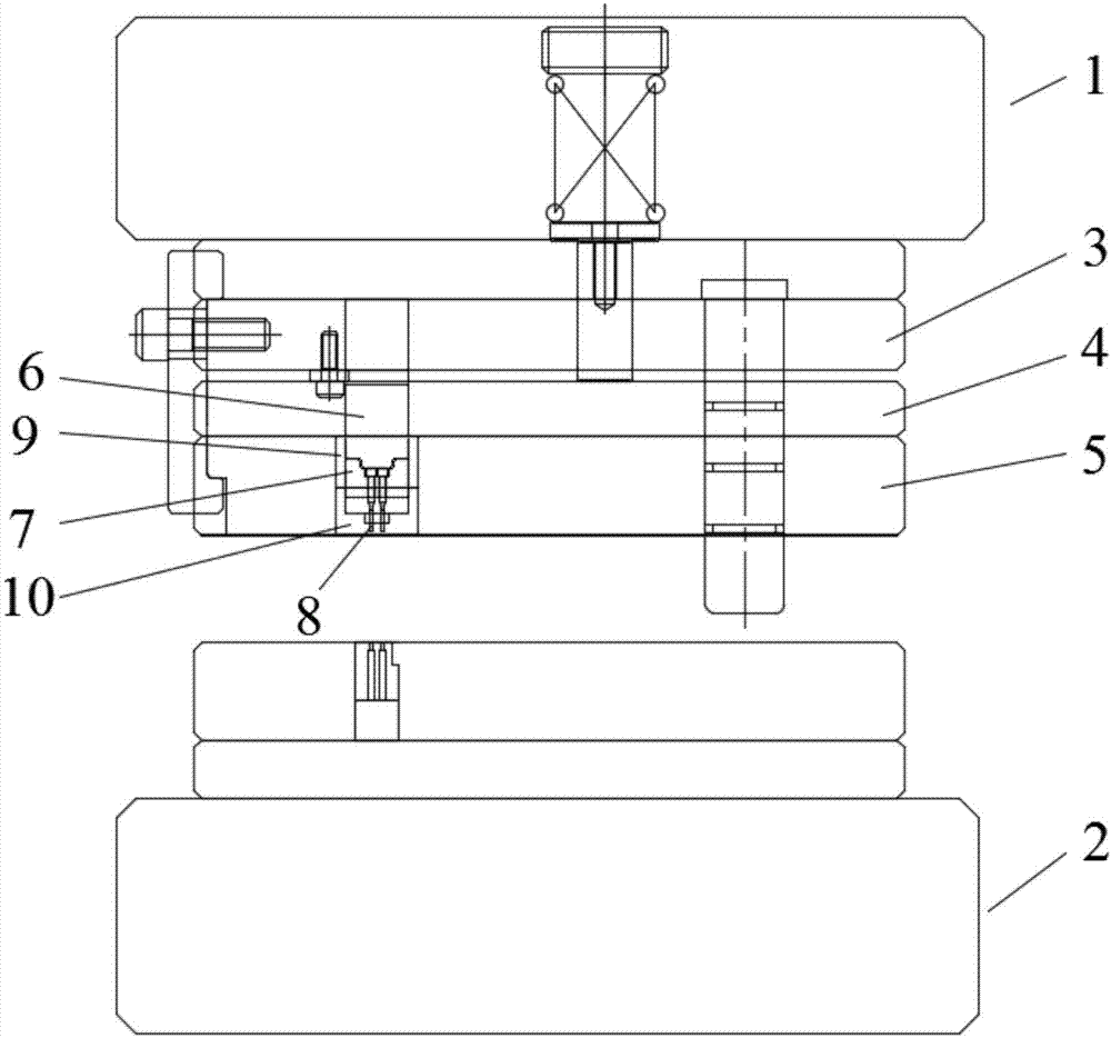
[0002] At present, the processing technology of sheet metal small holes (<φ1.0) mostly adopts etching or drilling, which is time-consuming and costly, and most sheet metal parts need to be bent. If etching or drilling is used, it needs to be bent with a mold , there will be errors in the secondary positioning; at present, the small hole punches in the mold are reinforced to enhance the strength of the punches, but the punches need to be fixed with a splint to guide the stripping plate, because the punch is long and the stripping guide part is too thin, the punching The head is very easy to break; the frequency of replacing the punch is high, resulting in waste of resources and increasing the processing cost, and the replacement of the punch requires dismantling the mold, which takes a long time to replace

Method used


Image

  • Small hole punching mechanism
  • Small hole punching mechanism

Examples


Embodiment

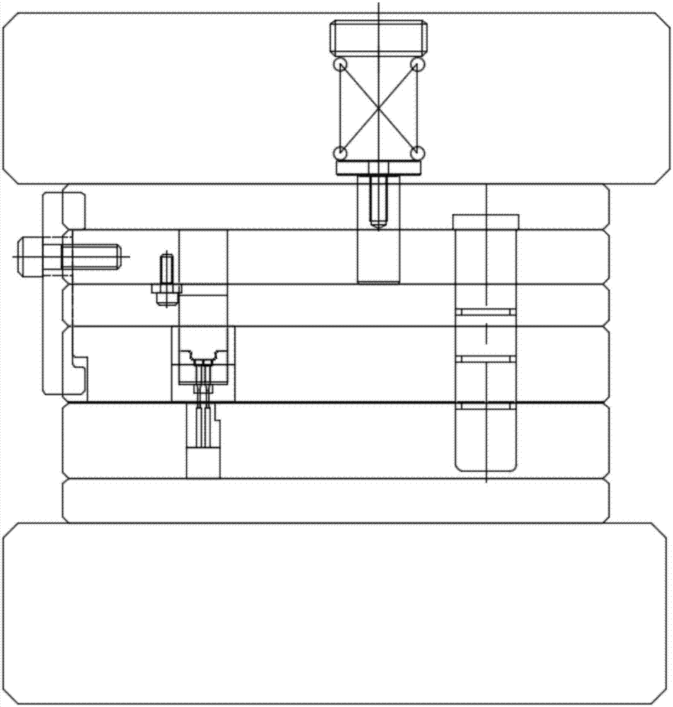
[0013] Such as figure 1 and figure 2 As shown, the present embodiment provides a small hole punching mechanism, which includes an upper die 1 and a lower die 2; the upper die 1 includes an upper clamping plate 3, a stopper plate 4, a stripping plate 5 and a punching device; The blanking device comprises a first punch clamping block 6, a second punch clamping block 7, a punch 8, a first off-board entry 9 and a second off-board entry 10; the first punch The clamping block 6 is connected with the second punch clamping block 7 through the dovetail groove slide table; the punch 8 is passed through the second punch clamp block 7, and the tail of the punch 8 is stuck in the dovetail groove slide table. Bottom; the first punch clamping block 6 and the second punch clamping block 7 are jointly installed in the upper clamping plate 3, the stopper plate 4 and the stripping plate 5, and the second stripping plate entry 10 is set On the underside of the first stripping insert 9; the fir...


PUM


Abstract

The invention relates to a small hole punching mechanism which comprises an upper die and a lower die, wherein the upper die comprises an upper clamping plate, a stopping plate, a stripping plate anda punching device; and the punching device comprises a first punching head clamping block, a second punching head clamping block, a punching head, a first stripping plate insert and a second strippingplate insert. The small hole punching mechanism provided by the invention has the beneficial effects that by adoption of the first punching head clamping block, the second punching head clamping block, the first stripping plate insert and the second stripping plate insert, the length of the punching head can be effectively shortened, the strength of the punching head can be improved, and the punching head breakage frequency can be reduced; the machining efficiency is high, the punching head can be directly replaced on a punching machine, the replacement time is short, the punching head need not be frequently replaced, the service life of the punching head is long, the waste of resources can be avoided, and the machining cost can be reduced; and the phenomenon that the punching of severalproducts is omitted can be avoided, the quantity of the products which are scrapped and need to rework can be reduced, the raw material utilization ratio can be improved, and the production cost can be reduced.

Description

technical field [0001] The invention relates to the field of sheet metal small hole processing, in particular to a small hole punching mechanism. Background technique [0002] At present, the processing technology of sheet metal small holes (<φ1.0) mostly adopts etching or drilling, which is time-consuming and costly, and most sheet metal parts need to be bent. If etching or drilling is used, it needs to be bent with a mold , there will be errors in the secondary positioning; at present, the small hole punches in the mold are reinforced to enhance the strength of the punches, but the punches need to be fixed with a splint to guide the stripping plate, because the punch is long and the stripping guide part is too thin, the punching The head is very easy to break; the frequency of replacing the punch is high, which causes waste of resources and increases the processing cost, and the replacement of the punch requires dismantling the mold, which takes a long time to replace. ...

Claims


Application Information

Patent Timeline
Patent Type & Authority Applications(China)
IPC IPC(8): B21D28/34
CPCB21D28/34
Inventor 陈盛辉韩博
Owner SUZHOU XINJIESHUN HARDWARE ELECTROMECHANICAL
Learn More