A Tightly Coupled Atomizer with Improved Atomization Efficiency and Reduced Droplet Diameter
An efficient and tightly coupled technology for atomization, applied in the field of pressure gas atomization liquid, can solve the problems of difficult industrial production, large nitrogen source and gas compressor, and increased production cost, and achieves improved strength, enhanced conversion efficiency, and reduced production costs. Small diameter effect
- Summary
- Abstract
- Description
- Claims
- Application Information
AI Technical Summary
Problems solved by technology
Method used
Image
Examples
Embodiment 1
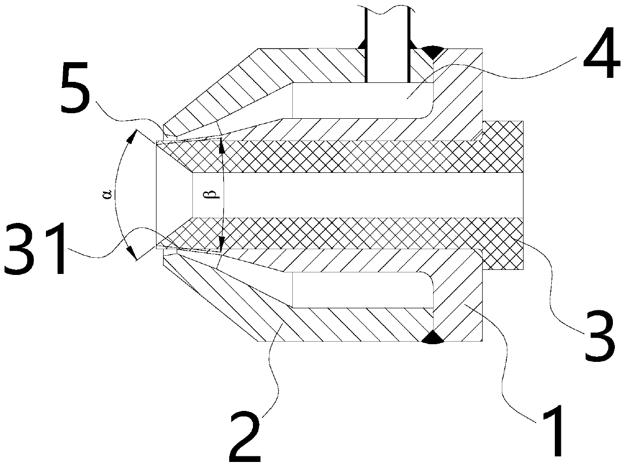
[0043] Embodiment one, as figure 1 As shown, this embodiment provides a close-coupled atomizer that improves atomization efficiency and reduces droplet diameter, including an upper body 1, a lower body 2, and a catheter 3 with a hollow tube structure, wherein the lower body 2 is sleeved on An airtight gas resident space 4 is formed outside the upper body 1 and between the upper body 1 ; the catheter 3 is arranged in the inner hole of the upper body 1 . The end surface of the conical body combined between the upper body and the lower body is provided with an annular slot type or an annular hole type gas nozzle 5 communicating with the gas resident space 4;
[0044] The inside of the outlet end of the catheter (the end of the catheter 31) is in the shape of a truncated cone with an enlarged opening, that is, an expansion outlet structure is formed inside the end of the catheter, and the expansion angle α is 30° to 150°; The inside of the liquid pipe can also be a circular strai...
Embodiment 2
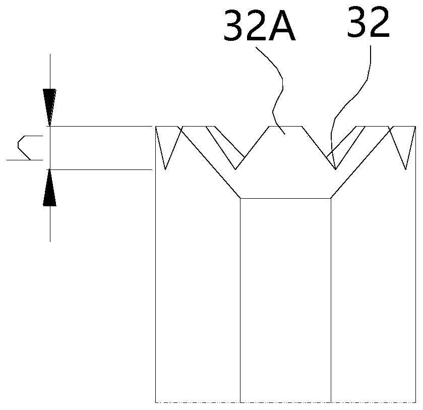
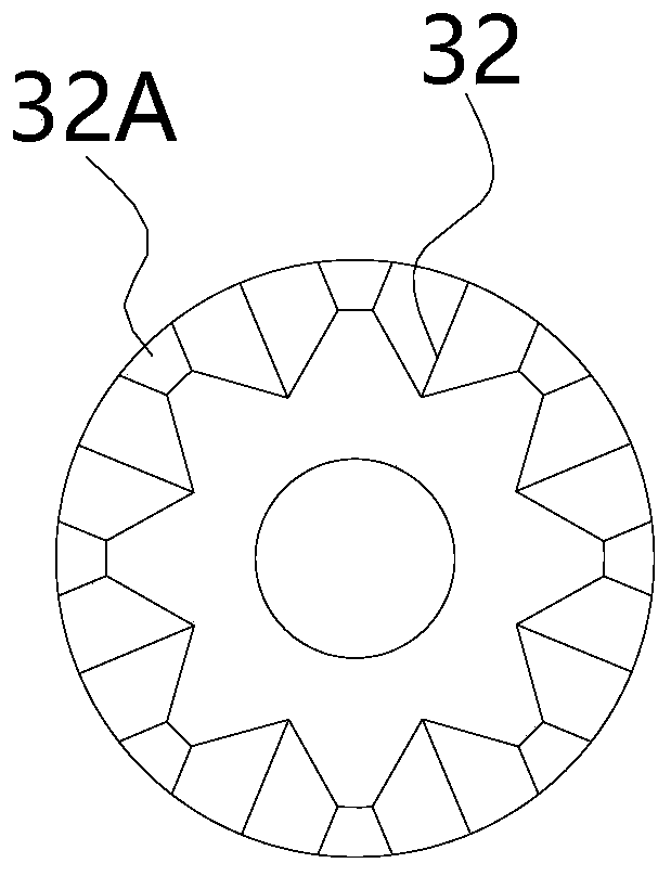
[0049] Embodiment two, such as figure 2 , 3 As shown, on the basis of Embodiment 1, the specific modification structure can be: a plurality of triangular grooves 32 of the same depth processed along the circumferential end surface of the catheter end 31 of the catheter 3, the triangular grooves 32 The two ends of the top edge of the top edge are respectively connected to the outer wall and the inner wall, and the triangular grooves 32 are arranged at intervals on the circumferential end surface of the catheter end 31, so that the catheter end 31 forms a zigzag shape. Wherein, the depth h of the triangular groove 32 (recessed depth relative to the catheter end 31) is 0.1-6mm, and the number is 2-40, and the adjacent triangular grooves 32 are not directly connected, but are connected through the original guide. The unmodified part of the end of the liquid pipe is connected, and this part is generally trapezoidal 32A, that is, the end surface of the end surface of the liquid pi...
Embodiment 3
[0051] Embodiment three, as Figure 4 , 5 As shown, on the basis of Embodiment 1, the modified structure can also be a plurality of triangular grooves 32 of the same depth processed along the circumferential end surface of the catheter end 31, and the two ends of the top edge of the triangular groove 32 are respectively connected. On the outer side wall and the inner side wall, the depth h of the triangular grooves 32 is 0.1-6mm, and the number is 2-40, and the adjacent triangular grooves 32 are directly connected by adjacent sides, and the connecting sides form an opposite direction 32B, that is, adjacent triangular grooves 32 are directly connected by their hypotenuses.
PUM
| Property | Measurement | Unit |
|---|---|---|
| depth | aaaaa | aaaaa |
| height | aaaaa | aaaaa |
| angle | aaaaa | aaaaa |
Abstract
Description
Claims
Application Information
 - R&D
- Intellectual Property
- Life Sciences
- Materials
- Tech Scout
- Unparalleled Data Quality
- Higher Quality Content
- 60% Fewer Hallucinations
Browse by: Latest US Patents, China's latest patents, Technical Efficacy Thesaurus, Application Domain, Technology Topic, Popular Technical Reports.
© 2025 PatSnap. All rights reserved.Legal|Privacy policy|Modern Slavery Act Transparency Statement|Sitemap|About US| Contact US: help@patsnap.com


