Loose fiber centrifugal dehydration dyeing device
A centrifugal dehydration and dyeing device technology, which is applied in the field of dyeing machines, can solve problems such as waste, insufficient dissolution, and increased power consumption, and achieve the effects of reducing washing times and time, improving dyeing quality, and reasonable structural design
- Summary
- Abstract
- Description
- Claims
- Application Information
AI Technical Summary
Problems solved by technology
Method used
Image

Examples
Embodiment 1
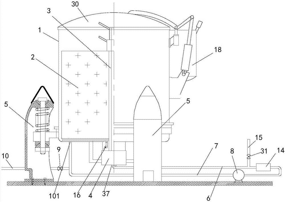
[0022] Embodiment 1: refer to Figure 1-5 . A kind of bulk fiber centrifugal dehydration dyeing device, comprises master vat 1 and circulation washing dyeing system, is provided with loose fiber cage 2 in master vat 1, and loose fiber cage 2 comprises central sleeve 2a and outer cylinder 2b, and central sleeve 2a is arranged on In the outer cylinder 2b, several small holes are evenly distributed on the central sleeve 2a and the outer cylinder 2b. The central sleeve 2a is provided with a central screw 3, and the main cylinder 1 is provided with a motor 4. The central screw 3 and the loose fiber cage 2. Tightly connected, the power output end of the motor 4 is connected to the central screw 3 through transmission and makes the central screw 3 rotate in the main cylinder 1 with the loose fiber cage 2. At least three groups of 1 connected to the suspension system 5, the water outlet end of the circulating washing and dyeing system communicates with the central sleeve 2a, and its ...
Embodiment 2
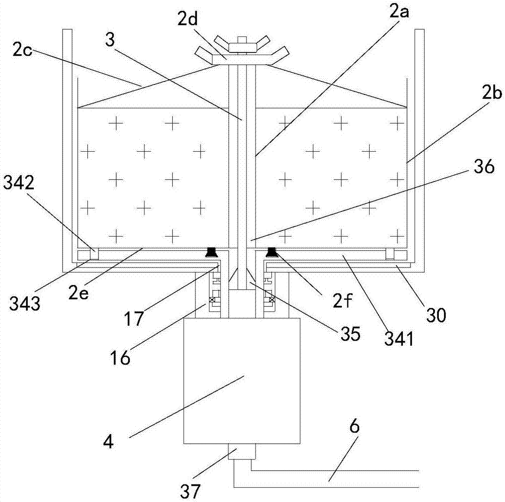
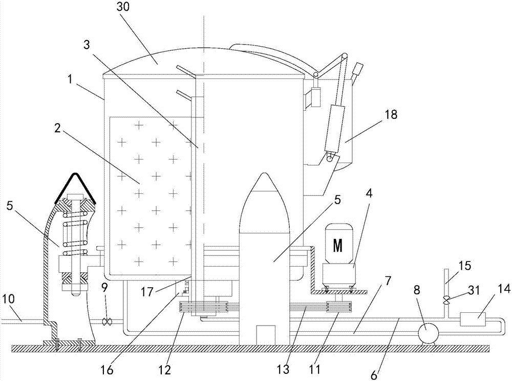
[0026] Embodiment 2: refer to figure 1 with 2. On the basis of Embodiment 1, the bottom of the master cylinder 1 is provided with a motor 4, and the bottom wall of the master cylinder 1 is provided with a mounting hole 17. The power output shaft of the motor 4 is a hollow shaft, and its upper end passes through the mounting hole 17. It is connected to the lower end of the central screw 3 through transmission, and the upper end of the power output shaft of the motor 4 and the installation hole 17 adopt a mechanical seal connection structure. The lower end between the outer sleeve 2b and the central sleeve 2a is connected by a sealing plate 2e. The inner bottom of the master cylinder 1 is provided with a disk portion 341, the power output shaft of the motor 14 is connected to the disk portion 341, and the top of the disk portion 341 is connected to the bottom of the sealing plate 2e. A soft sealing gasket 2f is provided between the sides, a number of positioning holes 343 open...
Embodiment 3
[0027] Embodiment 3: refer to image 3 and 4 . On the basis of Embodiment 1, an installation hole 17 is provided on the bottom wall of the main cylinder 1, a connecting seat 16 is provided at the bottom of the main cylinder 1, and a rotating hollow shaft 34 is arranged in the connecting seat 16, and the rotating hollow shaft 34 is connected with the installation A mechanical seal connection structure is adopted between the holes 17. After the lower end of the central screw 3 passes through the mounting hole 17, it is fixedly connected to the inner wall of the rotating hollow shaft 34 through several ribs 35 in the radial direction. The connection between the central screw 3 and the central sleeve 2a The gap between the ribs and the ribs 35 are used as the flow channel 36, and the water outlet of the circulating washing and dyeing system is connected to the lower end of the rotating hollow shaft 34 through the rotary joint 37, and the motor 4 is connected to the rotating hollo...
PUM
 Abstract
Description
Claims
Application Information
 - R&D
- Intellectual Property
- Life Sciences
- Materials
- Tech Scout
- Unparalleled Data Quality
- Higher Quality Content
- 60% Fewer Hallucinations
Browse by: Latest US Patents, China's latest patents, Technical Efficacy Thesaurus, Application Domain, Technology Topic, Popular Technical Reports.
© 2025 PatSnap. All rights reserved.Legal|Privacy policy|Modern Slavery Act Transparency Statement|Sitemap|About US| Contact US: help@patsnap.com