Electrical self-control system of sludge pumping device

An automatic control system and sludge pump technology, applied in pump control, liquid variable capacity machinery, machines/engines, etc., can solve problems such as poor safety, secondary pollution, and few equipment, and achieve less control wiring and simple installation. , the effect of easy archiving

Inactive Publication Date: 2018-05-08
长沙紫宸科技开发有限公司
View PDF4 Cites 1 Cited by
  • Summary
  • Abstract
  • Description
  • Claims
  • Application Information

AI Technical Summary

Problems solved by technology

[0003] At present, there are two most advanced sludge treatment methods in the world. One is to use sludge drying and reduction as fuel, and the other is to use sludge anaerobic treatment to generate gas. However, due to high energy consumption and large investment , there are problems such as secondary pollution, and currently there are few actual treatment technologies and equipment
Aiming at the problem of environmental pollution caused by a large amount of sludge containing organic matter, sludge modification and homogenization have been studied as a fuel energy technology. An important device in energy technology is a sludge pumping device, which is aimed at sludge pumps. The control of the transmission device cannot simply use various button switches, because this method is too simple, the safety is poor, the wiring is cumbersome and complicated, and only basic functions can be realized.

Method used


Image

  • Electrical self-control system of sludge pumping device
  • Electrical self-control system of sludge pumping device
  • Electrical self-control system of sludge pumping device

Examples


Embodiment Construction

[0027] The present invention will be further described in detail below in conjunction with the accompanying drawings and specific embodiments.

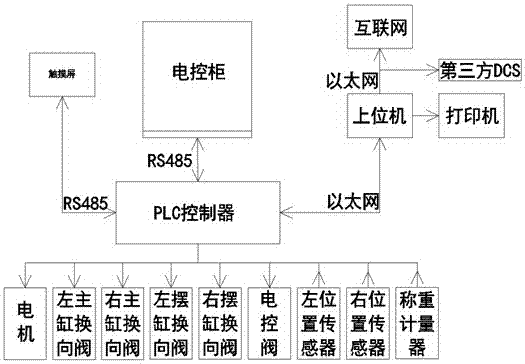
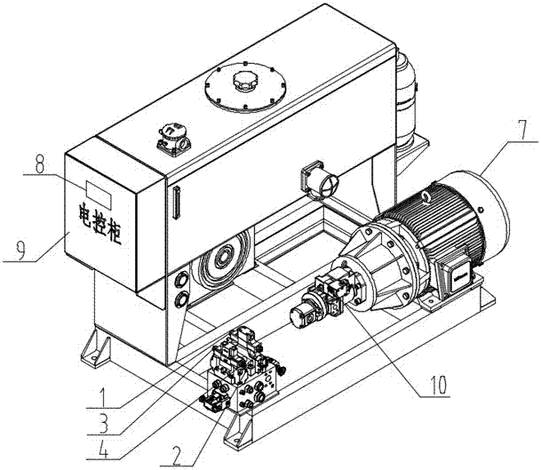
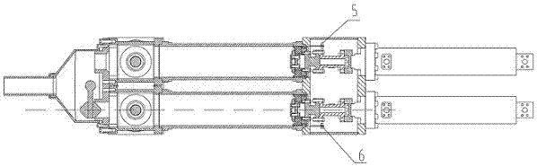
[0028] refer to Figure 1-3 , this embodiment includes left master cylinder reversing valve 1, right master cylinder reversing valve 2, left swing cylinder reversing valve 3, right swing cylinder reversing valve 4, left position sensor 5, right position sensor signal 6, motor 7 , touch screen 8, electric control cabinet 9, hydraulic control valve / electric control valve 10; the touch screen 8 is installed on the door of the electric control cabinet 9, the PLC controller is installed in the electric control cabinet 9, and the front end of the motor 7 is equipped with a hydraulic control valve / Electric control valve 10, left master cylinder reversing valve 1, right master cylinder reversing valve 2 are installed on both ends of the main cylinder valve block of the sludge pump, left swing cylinder reversing valve 3, right swing cylinder ...


PUM


Abstract

The invention discloses an electrical self-control system of a sludge pumping device. The electrical self-control system comprises a left main cylinder reversing valve, a right main cylinder reversingvalve, a left swing cylinder reversing valve, a right swing cylinder reversing valve, a left position sensor, a right position sensor signal, a motor, a touch screen, an electric control cabinet, a hydraulic-control valve/electric-control valve and a PLC controller, wherein the hydraulic-control valve/electric-control valve is arranged at the front end of the motor; the left main cylinder reversing valve and the right main cylinder reversing valve are arranged at the two ends of a main cylinder valve block of a sludge pump; the left swing cylinder reversing valve and the right swing cylinderreversing valve are arranged at the two ends of a swing cylinder valve block of the sludge pump; the left position sensor and the right position sensor signal are arranged at left and right sides of awater tank cover plate on the main cylinder end part of the sludge pump; the motor, the left main cylinder reversing valve, the right main cylinder reversing valve, the left swing cylinder reversingvalve, the right swing cylinder reversing valve, the hydraulic-control valve/electric-control valve, the left position sensor and the right position sensor signal are separately connected with the PLCcontroller; and the PLC controller is connected with the touch screen and the electric control cabinet. The electrical self-control system is high in safety, is simple in wiring, is complete in function, and is high in intelligent degree.

Description

technical field [0001] The invention relates to the technical field of industrial machinery, in particular to an electric automatic control system of a sludge pumping device. Background technique [0002] Since the late 1990s, my country's urban sewage treatment business has developed rapidly, and many urban sewage treatment plants have been built. At present, the dewatered sludge (water content 80%) produced by my country's established sewage treatment plants has exceeded 30 million tons / year. The main treatment methods for these organic matter-containing sludge include ocean and culvert dumping, sanitary landfill, solidified stacking, sludge composting, sludge drying, incineration, etc. A small amount of ceramsite, brick burning and anaerobic treatment biogas. [0003] At present, there are two most advanced sludge treatment methods in the world. One is to use sludge drying and reduction as fuel, and the other is to use sludge anaerobic treatment to generate gas. However...

Claims


Application Information

Patent Timeline
Patent Type & Authority Applications(China)
IPC IPC(8): F04B49/06
CPCF04B49/065
Inventor 尹小林何建辉
Owner 长沙紫宸科技开发有限公司
Why Eureka
Try Eureka