
Dual-cavity type electric energy storage heating system

A heat supply system and heat storage furnace technology, which is applied in the field of electric heating equipment, can solve the problems of poor heat preservation effect, small heat storage, and low heat storage temperature, and achieve the effects of enhanced heat preservation effect, controllable power, and simple structure

Pending Publication Date: 2018-05-08
李勇强
View PDF0 Cites 0 Cited by
  • Summary
  • Abstract
  • Description
  • Claims
  • Application Information

AI Technical Summary

Problems solved by technology

[0002] With the increasing demand for electricity, the peak-to-valley load difference of the power grid is also becoming more and more significant, which leads to a power gap during the peak of the daytime power consumption, and some power is wasted at night. This load difference is simply to increase the installed capacity. unsolvable
[0003] At present, electric energy storage heating technology has many shortcomings, which are manifested in the following aspects: 1. The heat storage temperature is low, and the heat storage capacity is small; 2. The heat preservation effect is poor, the heat loss is large, and the thermal efficiency is low; 3. There are serious problems. 4. It is difficult to maintain vulnerable parts (such as heating wires); 5. The temperature of the metal air chamber connected to the heat storage body is high, and the metal air chamber has poor oxidation and corrosion resistance
The defects of the above technologies and functions have affected the popularization and application of this product

Method used


Image

  • Dual-cavity type electric energy storage heating system
  • Dual-cavity type electric energy storage heating system
  • Dual-cavity type electric energy storage heating system

Examples


Embodiment Construction

[0027] Specific embodiments of the present invention will be described below.

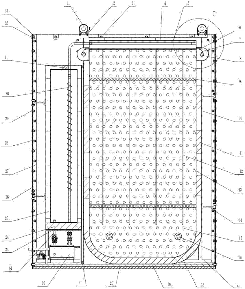
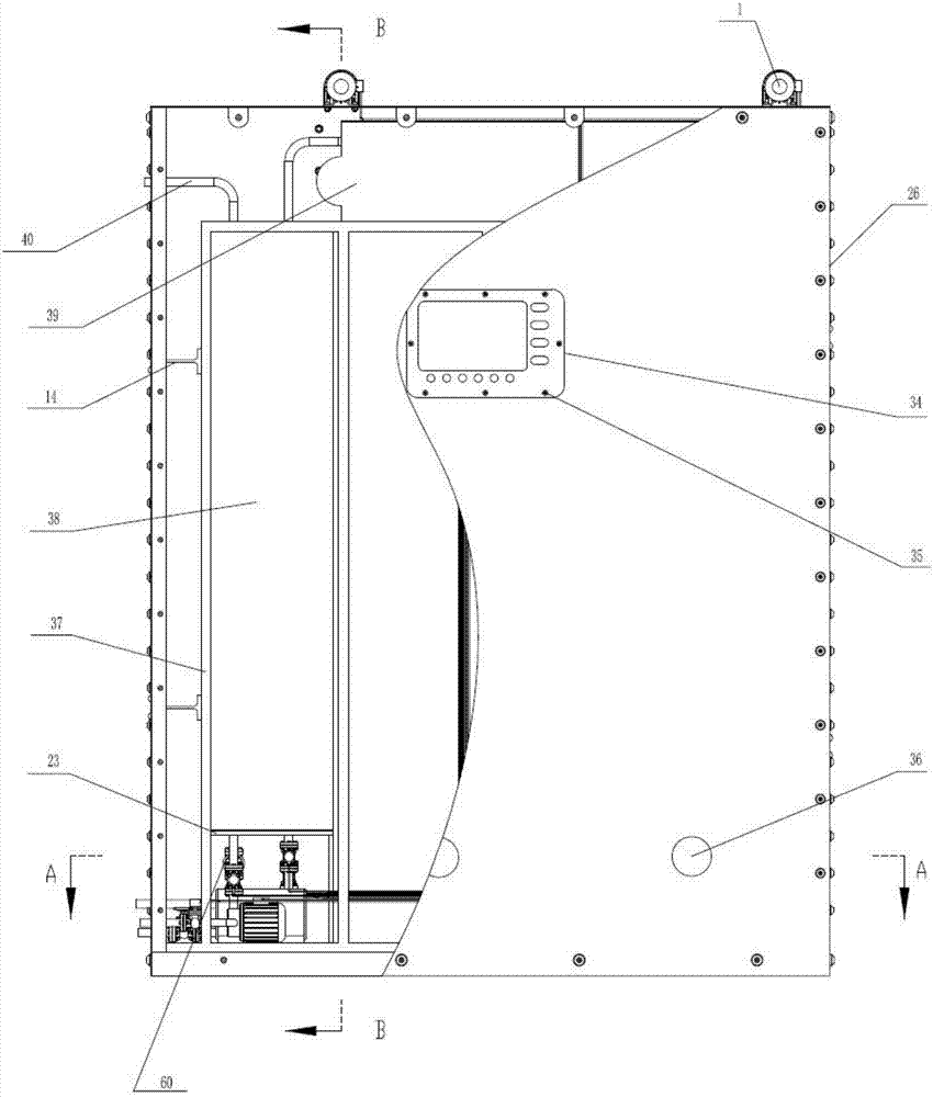
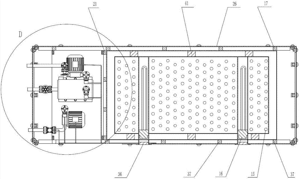
[0028] like figure 1 , figure 2 As shown, the double-chamber electric energy storage heating system includes a box shell 26 with a control panel 34, the control panel 34 is fixed on the outer surface of the box shell 26 by the third round head screw 35, and the box shell 26 The top is affixed to the upper cover 3 of the box body through the second round head screw 32 and the second welded hexagon nut 33. The bottom cover 20 of the box body is arranged at the bottom of the box body shell 26, and the outside of the regenerative furnace is arranged inside the box body shell 26. Liner 10, a regenerative furnace liner 13 is set inside the regenerative furnace outer liner 10, a hollow layer is formed between the regenerative furnace outer liner 10 and the regenerative furnace liner 13, and the first asbestos strip is installed on the top of the hollow layer 4. Install the second asbestos strip 11 on t...


PUM


Abstract

The invention relates to a dual-cavity type electric energy storage heating system. The dual-cavity type electric energy storage heating system comprises a box body shell with a control panel, a heatstorage furnace outer container is arranged inside the box body shell, a heat storage furnace inner container is arranged inside the heat storage furnace outer container, and a hollow layer is formedbetween the heat storage furnace outer container and the heat storage furnace inner container; a heat storage furnace, reflective plates, a heat storage medium with a heat-conducting structure and electrical heated tubes are correspondingly arranged from top to bottom inside the heat storage furnace outer container, a heat-absorbing coating and a reflective coating are applied on the left and right plate surfaces at the bottom of the reflective plates correspondingly, the reflective plates are linearly displaced by a sprocket drive mechanism controlled by a motor, so that the size of a heat release area at the top of the heat storage furnace can be controlled; oil transporting fin tubes are arranged in the heat storage furnace and are distributed in a waveform. According to the dual-cavitytype electric energy storage heating system, low valley power is fully utilized to heat the heat storage medium through the electrical heated tubes at night; during peak hours of electricity use in the daytime, the heat storage medium is used as a heat source to continuously provide indoor heat; and the cost can be saved by 29.6% compared to 24 hours of continuous heating by using the dual-cavitytype electric energy storage heating system.

Description

technical field [0001] The invention relates to the field of electrothermal equipment, in particular to a dual-cavity electric energy storage heating system integrating heat storage and heat utilization during electrothermal conversion. Background technique [0002] With the increasing demand for electricity, the peak-to-valley load difference of the power grid is also becoming more and more significant, which leads to a power gap during the peak of the daytime power consumption, and some power is wasted at night. This load difference is simply to increase the installed capacity. unsolvable. [0003] At present, electric energy storage heating technology has many shortcomings, which are manifested in the following aspects: 1. The heat storage temperature is low, and the heat storage capacity is small; 2. The heat preservation effect is poor, the heat loss is large, and the thermal efficiency is low; 3. There are serious problems. 4. The maintenance of vulnerable parts (such...

Claims


Application Information

Patent Timeline
Patent Type & Authority Applications(China)
IPC IPC(8): F24H7/04F24H9/18F24H9/20F24D13/00F24D19/10
CPCF24D13/00F24D19/1096F24H7/0433F24H9/1818F24H9/2014F24D2200/08
Inventor 李勇强李靖陈东辉汪旭徐莉
Owner 李勇强
Learn More