Vehicle-mounted mobile constant-temperature liquid cooling source device

A technology of cold source device and constant temperature liquid, used in refrigerators, refrigeration components, refrigeration and liquefaction, etc., can solve the problems of difficult troubleshooting, unfavorable factors in the service life of compressors, and large space occupation, so as to reduce energy consumption and compression. machine failure rate, improve transportation reliability, easy maintenance and disassembly

Pending Publication Date: 2018-05-08
扬州海通电子科技有限公司
View PDF0 Cites 3 Cited by
  • Summary
  • Abstract
  • Description
  • Claims
  • Application Information

AI Technical Summary

Problems solved by technology

[0003] 1) It takes up a lot of space, the integration level is not high, and it is not easy to troubleshoot and repair;
[0004] 2) Due to the adoption of common control methods without hot gas bypass and refrigerant flow regulation technology, precise control of the coolant supply flow and supply temperature cannot be achieved, and the temperature of the output refrigerant water fluctuates greatly, and the cooled object is suddenly cold and suddenly Severe heat phenomenon;
[0005] 3) Due to the use of compressor refrigeration, when the ambient temperature is lower than 0°C, the heat of the electronic equipment can only be taken away by the compressor to maintain the operating temperature of the electronic equipment, and the natural cooling of the ambient wind cannot be effectively used, and the energy of the cooling system The consumption cannot be reduced, and there are some unfavorable factors for the service life of the compressor.

Method used


Image

  • Vehicle-mounted mobile constant-temperature liquid cooling source device
  • Vehicle-mounted mobile constant-temperature liquid cooling source device
  • Vehicle-mounted mobile constant-temperature liquid cooling source device

Examples


Embodiment 1

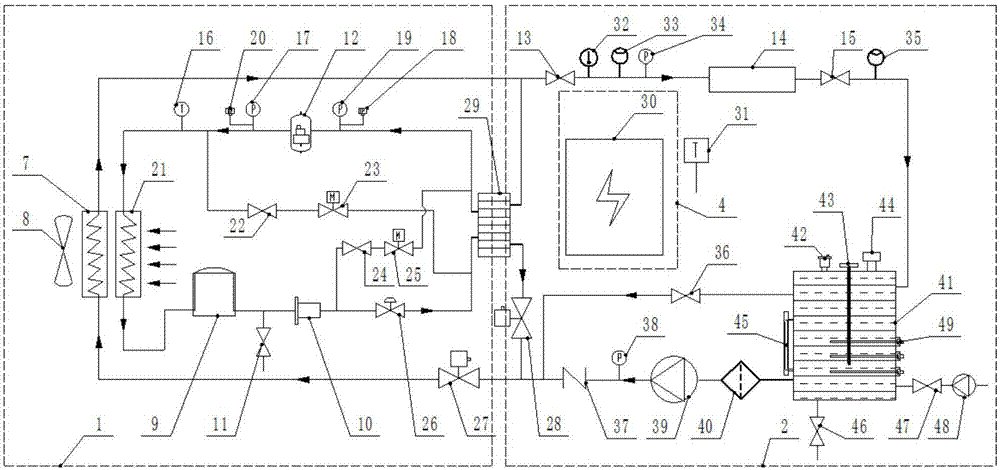
[0026] As shown in the figure, a vehicle-mounted mobile constant temperature liquid cooling source device includes a refrigeration unit 1, a water cooling unit 2, a frame 3 and an electrical control unit 4, and the refrigeration unit 1, the water cooling unit 2 and the electrical control unit 4 are arranged in the frame 3 , the frame 3 is placed in the vehicle-mounted shelter, and shock absorbers are arranged at the bottom and back of the frame 3 .

[0027] The refrigeration unit 1 includes two refrigeration routes to ensure that the water cooling unit 1 outputs constant-temperature refrigerant water, namely, the route for cooling and outputting refrigerant water through the compressor 12 in cooperation with the plate evaporator 29 and the route for cooling and outputting refrigerant water directly through the conventional heat exchanger 7 using ambient air cooling route. The route of the compressor 12 and the plate evaporator 29 in the refrigeration unit 1 is controlled by th...

Embodiment 2

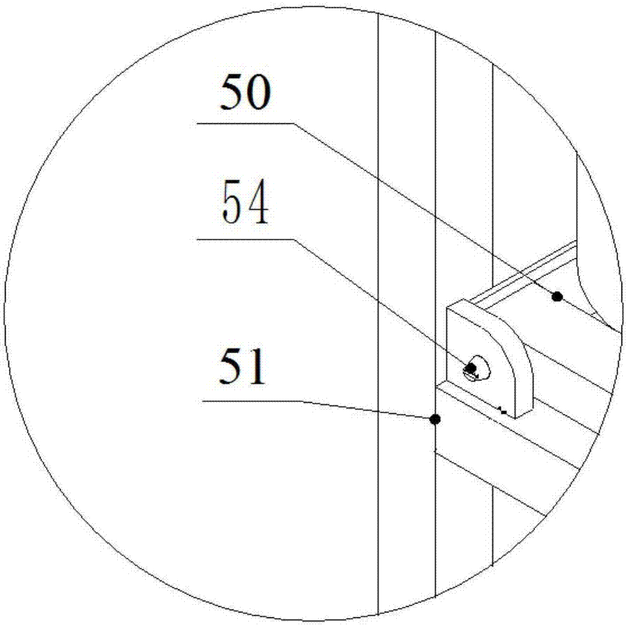
[0032] Embodiment 2 On the basis of Embodiment 1, a frame beam 51 is set in the middle of the frame 3, and the frame 3 is divided into upper and lower parts. The refrigeration unit 1 is installed on one side of the upper part of the frame 3, and the electrical appliance is installed on the other side of the upper part of the frame 3. The control unit 4, the water cooling unit 2 is installed on the lower part of the frame 3. During the installation process, the refrigeration unit 1 and the water-cooling unit 2 are placed on two independent frame modules respectively, and the frame module beam 50 is set at the bottom of the two frame modules, and a positioning pin 54 is set at one end of the frame module beam 50, and a locking block is set at the other end 62. Roller installation shaft 55 and roller 52 are installed at the bottom. The roller 52 is installed in the installation shaft 55 through the nut 53. The two frame modules are respectively pushed to the appropriate position o...

Embodiment 3

[0034] Embodiment 3 On the basis of Embodiments 1 and 2, shock absorbers are provided on the bottom and back of the frame 3 , and the liquid cooling source frame 3 is connected to the vehicle-mounted shelter 6 through the shock absorber 5 .


PUM


Abstract

The invention discloses a vehicle-mounted mobile constant-temperature liquid cooling source device which comprises a cooling unit, a water cooling unit, an environmental temperature sensor and an electrical control unit, wherein the cooling unit, the water cooling unit, the environmental temperature sensor and the electrical control unit are integrated in a frame; the cooling unit, the water cooling unit and the environmental temperature sensor are all electrically connected with the electrical control unit; and the cooling unit is connected with the water cooling unit through a heat exchangerand a plate-type evaporator. By adoption of the vehicle-mounted mobile constant-temperature liquid cooling source device disclosed by the invention, the flow rate and the cooling liquid temperature can be accurately controlled; the device integration level can be improved; and the energy consumption can be lowered.

Description

technical field [0001] The invention relates to cooling technology, in particular to a vehicle-mounted mobile constant temperature liquid cold source device. Background technique [0002] Conventional vehicle-mounted electronic equipment has the problem of high heat during operation. If the heat is not taken away in time, its working performance will be affected. The common way is to use fans to cool electronic equipment naturally. This method has low air supply pressure and long cooling time. , the cooling capacity is limited, it can only meet the electronic devices with general heat generation, and the cooling effect on electronic equipment with large heat generation is not good, which will affect its normal operation. For the on-board electronic equipment with large heat generation, the cooling method currently used often adopts a separate design of refrigeration cabinets and water-cooling cabinets, which has the following problems: [0003] 1) It takes up a lot of space...

Claims


Application Information

Patent Timeline
Patent Type & Authority Applications(China)
IPC IPC(8): F25B1/00F25B41/04F25B49/02F25B41/20
CPCF25B1/005F25B49/02F25B2600/25F25B2700/21F25B41/20
Inventor 王立慧冯静李唐史晓永许兆林丁俊
Owner 扬州海通电子科技有限公司
Why Eureka
Try Eureka