Steel rail flaw detection ultrasonic waveguide inclined probe and flaw detection method thereof

A technology of ultrasonic guided wave and oblique probe, which is applied to the analysis of solids using sound waves/ultrasonic waves/infrasonic waves, material analysis using sound waves/ultrasonic waves/infrasonic waves, and measuring devices. Problems such as low guided wave mode recognition and inapplicability to production practice have achieved high flaw detection efficiency, easy promotion, and low cost

Pending Publication Date: 2018-05-08
DONGGUAN UNIV OF TECH
View PDF11 Cites 5 Cited by
  • Summary
  • Abstract
  • Description
  • Claims
  • Application Information

AI Technical Summary

Problems solved by technology

[0005] I Bartoli et al., J Zhang et al., Lu Chao et al. used the hammering method to conduct ultrasonic guided wave flaw detection of rails. However, in the guided wave signal obtained by the hammering method, the modal recognition degree of the guided wave is low, so the guided wave receiving transduction is required. The sensor is close to the damage point, which is often difficult to achieve in actual detection
In addition, the hammering method is not suitable for production practice
[0006] In recent years, non-contact ultrasonic guided wave flaw detection based on laser ultrasonic and air coupling has also made great progress, but there are still obvious defects in signal-to-noise ratio, accuracy, and generalizability.

Method used


Image

  • Steel rail flaw detection ultrasonic waveguide inclined probe and flaw detection method thereof
  • Steel rail flaw detection ultrasonic waveguide inclined probe and flaw detection method thereof
  • Steel rail flaw detection ultrasonic waveguide inclined probe and flaw detection method thereof

Examples


Embodiment 1

[0070] This embodiment provides an ultrasonic guided wave inclined probe, which is used for rail head flaw detection. Compared with the traditional ultrasonic rail flaw detection technology, the single detection distance is longer, and the typical single detection distance can reach ten meters. To tens of meters, the flaw detection efficiency is high.

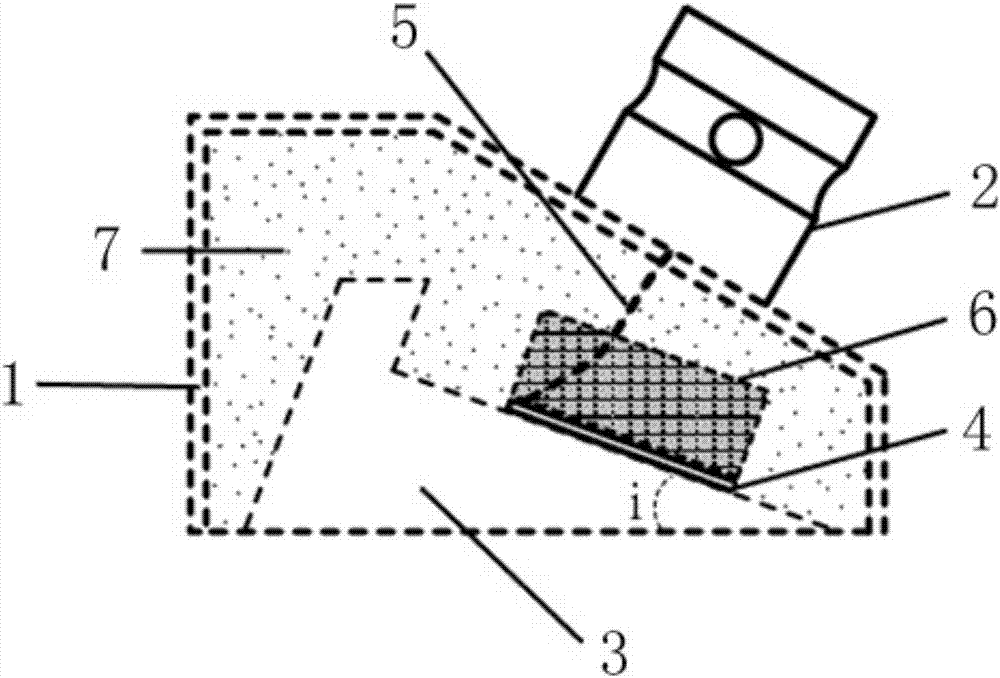
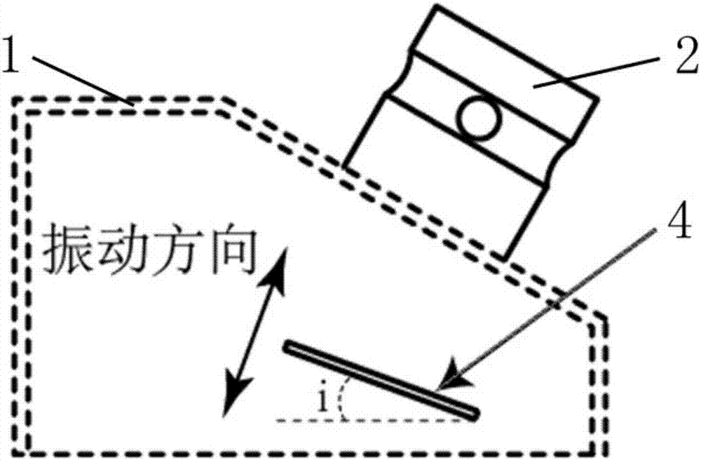
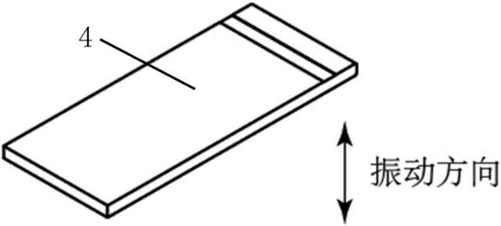
[0071] Such as figure 1 with figure 2 As shown, the ultrasonic guided wave angle probe of this embodiment includes a housing 1, a piezoelectric unit and an interface 2, and the piezoelectric unit includes a wedge 3, a piezoelectric wafer 4, a cable 5 and a damping block 6, for clarity See the position of the piezoelectric wafer 4 in the shell 1, in figure 2 Only the shell 1, the interface 2 and the piezoelectric chip 4 are shown in the figure, while other parts are omitted.

[0072] One surface of the wedge 3 forms an included angle i with the horizontal plane, and the included angle i in this embodiment is 41 degrees.

...

Embodiment 2

[0093] The main features of this embodiment are: the structure of the ultrasonic guided wave oblique probe is the same as that of Embodiment 1, such as Figure 11As shown, it is used for rail head flaw detection, but there are two ultrasonic guided wave oblique probes 8, and the two ultrasonic guided wave oblique probes 8 are placed longitudinally (along the length direction of the rail) on the upper surface of the rail head tread of the rail 9, and placed on the Ultrasonic detection couplant is used between the ultrasonic guided wave inclined probe 8 and the rail 9 to ensure the detection effect, and the interfaces 2 of the two ultrasonic guided wave inclined probes 8 are respectively connected to the excitation channel and the receiving channel of the external device 10, and the external device 10 The ultrasonic guided wave inclined probe 8 connected to the excitation channel, in the detection, the piezoelectric chip 4 realizes the excitation of the guided wave through the in...

Embodiment 3

[0095] The main features of this embodiment are: the structure of the ultrasonic guided wave oblique probe is the same as that of Embodiment 1, such as Figure 12 As shown, for rail head flaw detection, two ultrasonic guided wave angled probes 8 are placed longitudinally (along the length direction of the rail) in the center on the upper surface of the rail head tread of the rail 9, and between the ultrasonic guided wave angled probes 8 and the rail 9 Ultrasonic detection couplant is used to ensure the detection effect, but the external equipment includes external excitation equipment 11 and external receiving equipment 12, that is, the excitation and reception functions of the signal are realized by different external equipment, and the interface of two ultrasonic guided wave inclined probes 8 2 respectively connected to the external excitation device 11 and the external receiving device 12, the ultrasonic guided wave inclined probe 8 connected to the external excitation devic...


PUM


Abstract

The invention discloses a steel rail flaw detection ultrasonic waveguide inclined probe and a flaw detection method thereof. The probe comprises a shell, a sound absorption filler, at least one dielectric unit and at least one interface, wherein each dielectric unit is arranged inside the shell and comprises a wedged block, a dielectric wafer, a cable wire and a damping block; the dielectric waferis a dielectric ceramic piece of a thickness vibration mode; an included angle is formed between one surface of the wedged block and the horizontal plane; one surface perpendicular to a vibration direction, of the dielectric wafer, is flatly adhered to the surface of the wedged block; the damping block is tightly adhered to another surface perpendicular to the vibration direction, of the dielectric wafer; the sound absorption filler is arranged inside a vacant space except the dielectric unit inside the shell; the interface is arranged on one surface of the shell and is connected with the dielectric wafer through the cable wire. Due to adoption of the dielectric wafer of the thickness vibration mode, the probe is high in signal to noise ratio, low in cost and convenient to popularize, inaddition can be applied to flaw detection on rail heads and rail bottoms, and is long in single detection distance.

Description

technical field [0001] The invention relates to a flaw detection device and a flaw detection method thereof, in particular to an ultrasonic guided wave angle probe for rail flaw detection and a flaw detection method thereof, belonging to the technical field of nondestructive testing. Background technique [0002] Rail flaw detection is one of the key tasks to ensure the safe operation of trains. At present, ultrasonic technology is generally used for rail flaw detection. The ultrasonic probe transmits pulsed sound waves from the rail head tread to the rail and receives its reflected waves to detect damage. Ultrasonic flaw detection technology can only inspect a local area around the probe each time pulsed sound waves are emitted, and there are large flaw detection blind spots on both sides of the rail bottom. Although rail head damage is still the main factor causing rail breakage, the number of rail breakage events or accidents caused by rail bottom damage has also shown a...

Claims


Application Information

Patent Timeline
Patent Type & Authority Applications(China)
IPC IPC(8): G01N29/24G01N29/28G01N29/04
CPCG01N29/04G01N29/245G01N29/28G01N2291/0234G01N2291/0289G01N2291/2623
Inventor 林荣马宏伟温宇立
Owner DONGGUAN UNIV OF TECH
Why Eureka
Try Eureka