
A tool for correcting the shape of engine load-bearing struts matched with heat treatment

A technology of engine and heat treatment temperature, used in heat treatment furnaces, heat treatment equipment, manufacturing tools, etc., to achieve the effects of convenient operation, lower production costs, and reduced scrap rate

Active Publication Date: 2019-08-02
AECC AERO SCI & TECH CO LTD
View PDF13 Cites 0 Cited by
  • Summary
  • Abstract
  • Description
  • Claims
  • Application Information

AI Technical Summary

Problems solved by technology

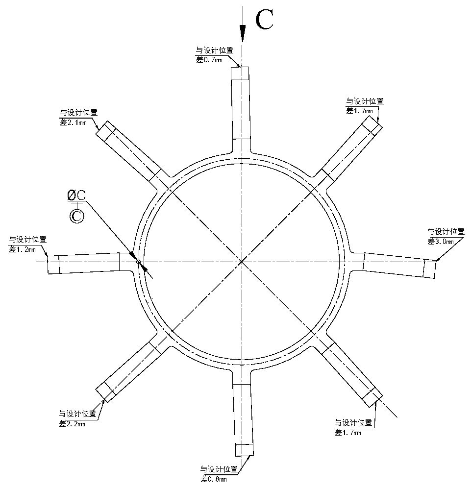
[0004] The purpose of the present invention is to provide a shape-correcting tool for the engine load-bearing strut that matches the heat treatment for the deformation of the existing inner load-bearing ring and load-bearing strut made of TC4 titanium alloy material after welding

Method used


Image

  • A tool for correcting the shape of engine load-bearing struts matched with heat treatment
  • A tool for correcting the shape of engine load-bearing struts matched with heat treatment
  • A tool for correcting the shape of engine load-bearing struts matched with heat treatment

Examples


Embodiment 1

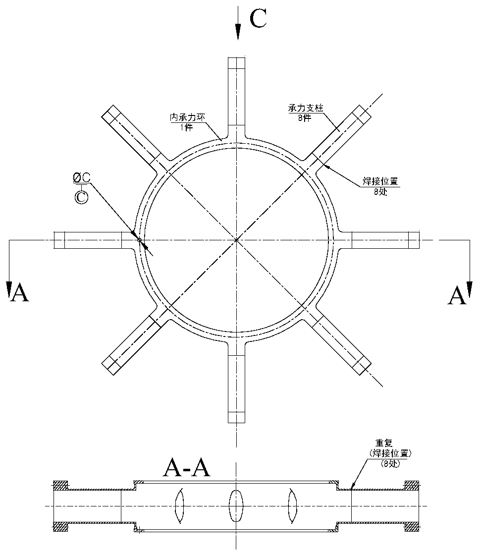
[0031] The shape-calibrating tooling of the engine load-bearing strut that matches the heat treatment provided in this embodiment is based on the welding between the inner load-bearing ring of a certain type of engine and 8 evenly distributed load-bearing struts, which need to be calibrated due to deformation. shape to design. Since there are 8 welding positions, such as figure 1 As shown, the structure of the designed correction tool is as follows Figure 5 As shown, it is specifically composed of a base 1 , a correction assembly, a pressing plate assembly and a positioning angle pin 22 .

[0032] Among them, the base 1 is a disc with a boss 2 in the middle, and an axial step through hole 3 is opened in the middle of the boss 2, and a pin hole 4 is opened on one side of the upper surface of the boss 2, and the pin hole is connected with the bottom surface of the inner bearing ring. The pin hole ΦC matches, and is connected and positioned by the positioning angle pin 22, se...

Embodiment 2

[0040] The structure of the correction tooling provided by this embodiment is basically the same as that of Embodiment 1, the difference is that: 1) there are 4 correction assemblies and pressure plate assemblies in this embodiment; 2) the inclination angle α of the inclined through hole is 30° , the angle α between the bevel at the front end of the wedge nail and the axis is also 30°; 3) The heat treatment temperature is 700°C, and the heat treatment time is 3 hours.

Embodiment 3

[0042] The structure of the correction tooling provided by this embodiment is basically the same as that of Embodiment 1, the difference is that: 1) there are 6 correction assemblies and platen assemblies in this embodiment; 2) the inclination angle α of the inclined through hole is 20° , the angle α between the bevel at the front end of the wedge nail and the axis is also 20°; 3) The heat treatment temperature is 750°C, and the heat treatment time is 1.5 hours.


PUM


Abstract

The invention discloses a shape correcting tool for force bearing supporting columns of an engine matched with heat treatment. The shape correcting tool is composed of a base, correcting assemblies, pressing plate assemblies and a positioning angle pin; a disc with a boss is arranged in the middle part of the base, and an axial step through hole is formed in the middle part of the boss; the correcting assemblies are matched with the force bearing supporting columns, the number of the correcting assemblies is at least four, and the correcting assemblies are uniformly distributed and fixedly connected to the surface of the disc around the boss of the base; the pressure plate assemblies is also matched with the force bearing supporting columns, the number of the pressure plate assemblies is at least four, and the pressure plate assemblies are uniformly and fixedly connected to the step of the through hole of the boss of the base; and after the welded force bearing supporting columns are assembled on the shape correcting tool according to the design requirements, the heat treatment is carried out, and then cooling is carried out. The shape correcting tool has the advantages of being simple in structure, easy to manufacture and very good in correcting effect, and the deformation of the force bearing supporting columns can be reduced to 0.3mm or less from 3 mm before shape correcting, so that welding parts meet the design and use requirements, the rejection rate is reduced, production cost is reduced, meanwhile, the blank of the shape correcting tool of the force bearing supporting columns is filled.

Description

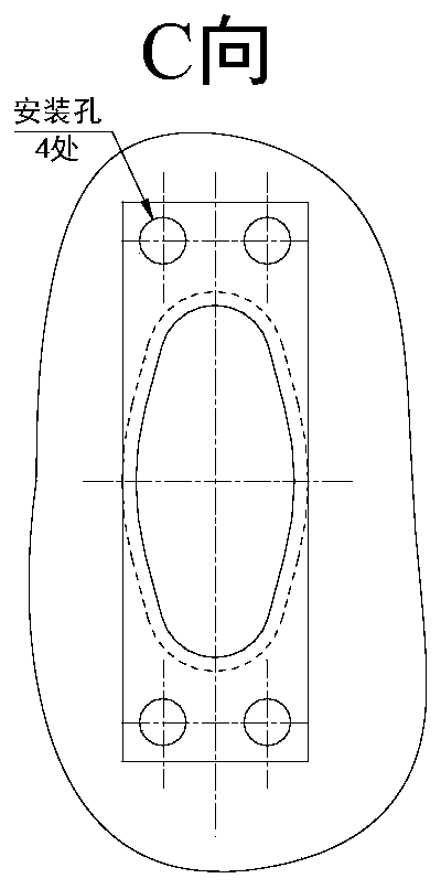
technical field [0001] The invention belongs to the technical field of manufacturing tools for aero-engine components, and in particular relates to a shape-calibrating tool for an engine load-bearing pillar matched with heat treatment. Background technique [0002] The connection between the inner bearing ring of a certain type of engine in my country and 8 evenly distributed bearing pillars is completed by argon arc welding. But when the inner load-bearing ring is welded with the 8 load-bearing pillars, there are 4 mounting holes that need to be processed correctly on the outer end surface of the load-bearing pillar. After processing, the wall thickness to the outer contour of the end surface meets the requirements of the design drawing The difference is large and cannot meet the design and use requirements. [0003] After analysis, it is found that the reason for this situation is that the inner load-bearing ring and the eight uniformly distributed load-bearing pillars ar...

Claims


Application Information

Patent Timeline
Patent Type & Authority Patents(China)
IPC IPC(8): B21D3/16C21D9/00
CPCB21D3/16C21D9/0068Y02P10/20
Inventor 乔雷张校宇张强程立蔡新陈鹏飞
Owner AECC AERO SCI & TECH CO LTD
Learn More