
Flame monitoring device for torch lamp

A technology of flame monitoring and permanent lights, which is applied in the field of flame monitoring in the petrochemical industry. It can solve the problems of affecting the life of the ignition system, high cost of flame monitoring, and being affected by weather conditions, so as to avoid interference from weather conditions, long service life and low cost.

Active Publication Date: 2021-02-09
CHINA PETROLEUM & CHEM CORP +1
View PDF4 Cites 1 Cited by
  • Summary
  • Abstract
  • Description
  • Claims
  • Application Information

AI Technical Summary

Problems solved by technology

[0003] The purpose of the present invention is to provide a flame monitoring device for torch lights to solve the problems of high cost of flame monitoring for torch lights, slow monitoring response, influence by weather conditions, inaccurate monitoring and affecting the life of the ignition system

Method used


Image

  • Flame monitoring device for torch lamp

Examples


Embodiment Construction

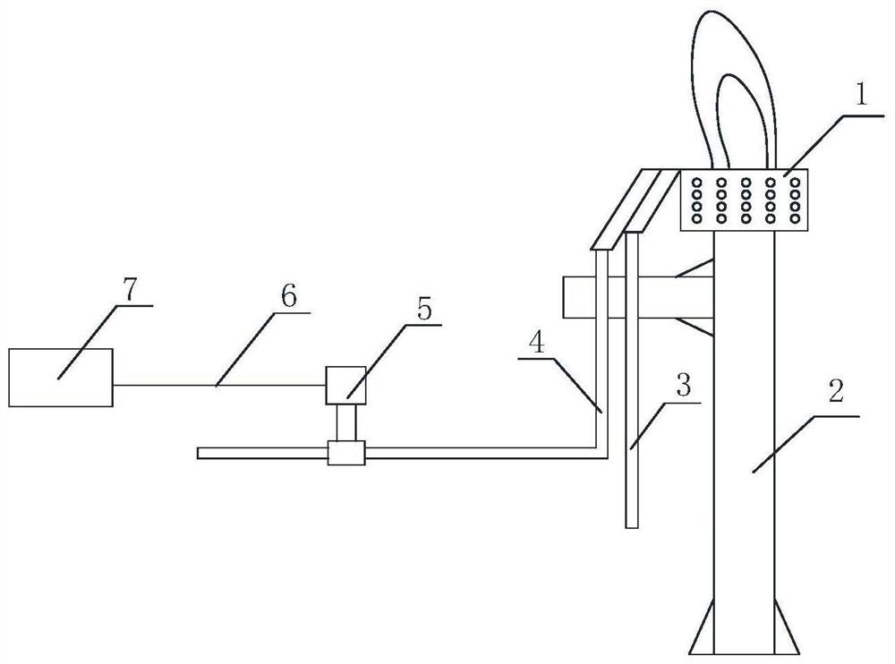
[0017] Such as figure 1 As shown, this embodiment provides a flame monitoring device for a flare lamp, which includes a lamp 1 , a flare tower 2 , a fuel pipeline 3 , a pilot pipeline 4 , a vibration sensor 5 and a processor 7 . The ever-burning lamp 1 is installed on the top of the torch tower 2, the bottom of the ever-burning lamp 1 is connected to the fuel pipeline 3 and the ignition pipeline 4, fuel gas is passed through the fuel pipeline 3, the ever-burning lamp 1 is always in a burning state, and is used to ignite the torch in an accident state, The ignition pipeline 4 is used for lighting the pilot lamp 1 . The vibration sensor 5 is an IEPE type vibration sensor 5, and the frequency response range of the vibration sensor 5 is 10kHz-100kHz. The vibration sensor 5 is connected to the processor 7 via a signal cable 6 . When the burning lamp 1 burns to produce a flame, it will emit a sound wave signal. The vibration sensor 5 receives the sound wave signal generated by the...


PUM


Abstract

The invention proposes a flame monitoring device for a torch light, comprising a light, a torch tower, a fuel pipeline, a pilot pipeline, a vibration sensor and a processor, the light is arranged on the top of the torch tower, the fuel pipeline and the fire pipeline are respectively connected to the light, the vibration sensor Signal connection processor. The invention has the beneficial effects of simple structure, convenient installation, long service life and low cost; the flame state monitoring has fast response speed, accurate monitoring and avoids being disturbed by weather conditions.

Description

technical field [0001] The invention relates to the technical field of flame monitoring in the petrochemical industry, in particular to a flame monitoring device for an ever-burning torch lamp. Background technique [0002] Keeping the burning state of the torch light is an important measure to ensure the safe handling of the torch gas during emergency release. If the light goes out and is not found in time or the ignition is not successful after discovery, it will bring safety hazards. At present, the technology for flame monitoring of torch lights can be divided into high-altitude monitoring system and ground monitoring system. The high-altitude monitoring system mainly includes a thermocouple monitoring system and a flame ion monitoring system, which mainly have the following problems: the flame monitoring sensors of the high-altitude monitoring system are all installed on the torch lamp, and under the action of high temperature and corrosion, the sensor life is short and...

Claims


Application Information

Patent Timeline
Patent Type & Authority Patents(China)
IPC IPC(8): G01J1/42
CPCG01J1/42G01J2001/4247
Inventor 张杰东于安峰鲍磊党文义王鹏韩中枢
Owner CHINA PETROLEUM & CHEM CORP
Learn More