Check patentability & draft patents in minutes with Patsnap Eureka AI!

A crowbar protection circuit for double-fed power generation system

A protection circuit and double-fed power generation technology, which is applied in wind power generation, circuit devices, AC network circuits, etc., can solve the problems of high cost, inability to switch off with current, and high voltage, and achieve low cost, high reliability, and simple structure Effect

Active Publication Date: 2020-11-10
天津瑞源电气有限公司
View PDF5 Cites 0 Cited by
  • Summary
  • Abstract
  • Description
  • Claims
  • Application Information

AI Technical Summary

Problems solved by technology

[0003] In the existing method, one is to use a three-phase rectifier bridge and a thyristor as a switching tube. Since the thyristor is a semi-controlled switching device, it cannot be turned off with current, so that once the crowbar is triggered, the rotor continues to be short-circuited. The unit must Shutdown, which cannot meet the needs of the doubly-fed unit to ride through the fault;
[0004] The second method is to replace the three-phase rectifier bridge with thyristors to realize the short circuit of the rotor. In this scheme, the zero-crossing point in the AC circuit is used to realize the shutdown of the crowbar. However, due to the low frequency of the rotor current, the timing of crowbar shutdown is uncertain. sex;
[0005] The third approach is to use IGBTs with anti-parallel diodes to replace the thyristors in the second method. This effectively solves the shortcomings of the above two methods and can meet the needs of fault ride-through of double-fed units. However, six IGBTs are required to Complete three-phase short-circuit turn-on, short-circuit and turn-off, with more IGBTs and higher cost;
However, since the crowbar needs to be directly connected to the rotor winding, when the IGBT is turned off at a high current, the rotor leakage inductance and the inductance of the wire connected to the rotor will generate a reverse peak voltage that is sufficient to cause the IGBT to be damaged by overvoltage, so the existing method is to use an RC The circuit is absorbing energy, but the voltage at the IGBT terminal is still high due to the addition of the resistor. If the resistance value is too small, the IGBT current will be too large when the IGBT is turned on, which may damage the IGBT.

Method used


Image

  • A crowbar protection circuit for double-fed power generation system
  • A crowbar protection circuit for double-fed power generation system
  • A crowbar protection circuit for double-fed power generation system

Examples


Embodiment Construction

[0023] It should be noted that, in the case of no conflict, the embodiments of the present invention and the features in the embodiments can be combined with each other.

[0024] The present invention will be described in detail below with reference to the accompanying drawings and examples.

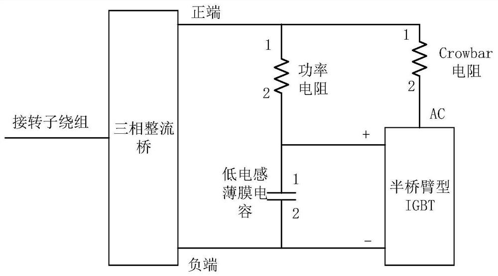
[0025] Such as figure 1 As shown, a Crowbar protection circuit for a double-fed power generation system includes a three-phase rectifier bridge, a half-bridge arm type IGBT, a Crowbar resistor, a resistor R1 and a capacitor C4. The AC side of the three-phase rectifier bridge is connected to the generator rotor winding. The positive end of the DC side is connected to one end of the Crowbar resistor, the negative end is connected to the negative end of the half-arm IGBT, the other end of the Crowbar resistor is connected to the AC end of the half-arm IGBT, and one end of the resistor R1 is connected to the three-phase The positive end of the DC side of the rectifier bridge is connected, a...


PUM


Abstract

The invention provides a Crowbar protection circuit for a doubly-fed power generation system, comprising a three-phase rectifier bridge, a half-bridge arm type IGBT, a Crowbar resistor, a resistor R1 and a capacitor C4, the AC side of the three-phase rectifier bridge is connected to the generator rotor winding , the positive end of the DC side is connected to one end of the Crowbar resistor, the negative end is connected to the negative end of the half-arm IGBT, the other end of the Crowbar resistor is connected to the AC end of the half-arm IGBT, and one end of the resistor R1 is connected to the three-phase rectifier bridge DC The positive terminal of the capacitor C4 is connected to the positive terminal of the half-bridge arm type IGBT, and the other terminal is connected to the negative terminal of the DC side of the three-phase rectifier bridge. The invention has beneficial effects: it can ensure that the half-bridge arm type IGBT will not bear high voltage, effectively perform crowbar protection on the rotor side of the motor, and has simple structure, low cost and high reliability.

Description

technical field [0001] The invention belongs to the technical field of circuit topology of a doubly-fed power generation system, and in particular relates to a Crowbar protection circuit for a doubly-fed power generation system. Background technique [0002] Since the stator side of the double-fed wind turbine is generally directly connected to the grid, the stator voltage of the generator will drop or rise with the drop or rise of the grid voltage when the grid fails, which will cause double-fed wind turbines. The stator flux linkage of the fed induction motor changes with the change of the stator voltage, but the stator flux linkage is a continuous inertial quantity, so when the power grid fails, the voltage can change suddenly, but the flux linkage cannot change suddenly, so that the stator flux linkage appears A transient DC component, this DC component will cause high voltage and high current on the rotor side, so if the rotor inverter is not protected, it will cause ov...

Claims


Application Information

Patent Timeline
Patent Type & Authority Patents(China)
IPC IPC(8): H02M1/34H02J3/38
CPCH02J3/386H02M1/34H02M1/348Y02E10/76
Inventor 陈海彬赵家欣问虎龙张春晓
Owner 天津瑞源电气有限公司
Features
  • R&D
  • Intellectual Property
  • Life Sciences
  • Materials
  • Tech Scout
  • Unparalleled Data Quality
  • Higher Quality Content
  • 60% Fewer Hallucinations
Learn More