Micro-fluidic chip template, preparation method thereof and application of template

A technology of microfluidic chips and templates, which is applied to chemical instruments and methods, laboratory containers, laboratory utensils, etc., can solve the problems of poor reproducibility, difficulty in ensuring experimental results, and increased experimental costs, so as to achieve simple production, The effect of simple preparation method and readily available materials

Active Publication Date: 2018-05-15
安徽中医药高等专科学校
View PDF5 Cites 6 Cited by
  • Summary
  • Abstract
  • Description
  • Claims
  • Application Information

AI Technical Summary

Problems solved by technology

[0004] However, the microfluidic chip needs to be cut and punched in the preparation process before it can be put into use. If manual cutting and punching are used, the reproducibility of each time ...

Method used


Image

  • Micro-fluidic chip template, preparation method thereof and application of template
  • Micro-fluidic chip template, preparation method thereof and application of template
  • Micro-fluidic chip template, preparation method thereof and application of template

Examples


Embodiment 1

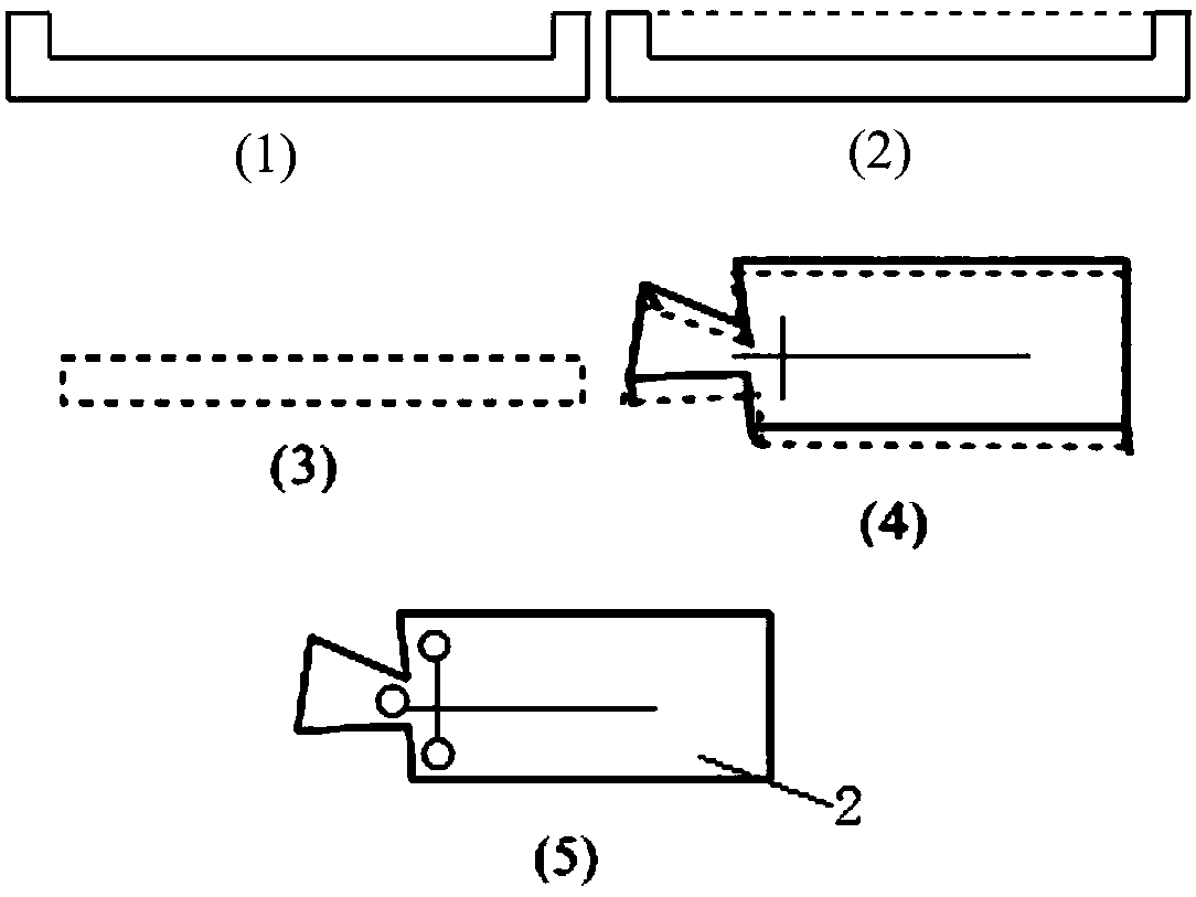
[0028] A kind of preparation method of microfluidic chip template

[0029] Step 1: If figure 1 As shown, the PDMS monomer and the curing agent are mixed at a mass ratio of 10:1 to obtain a PDMS prepolymer, which is injected onto the GaAs male mold with a convex cross-shaped microchannel, vacuumed and left for 25-35 minutes to remove air bubbles. Heating for 2 hours to solidify the PDMS prepolymer, and then peel off from the GaAs positive mold to obtain a solid PDMS prepolymer with concave cross-shaped micro-channels, cut, and punch a hole at each of the three ports adjacent to the concave cross-shaped micro-channels , respectively serving as the sample pool, the buffer pool, and the waste pool to prepare the microfluidic chip 2;

[0030] Step 2: If figure 2 As shown, the microfluidic chip 2 prepared in step 1 is placed in the open silica gel mold 1, so that the surface of the microfluidic chip 2 with the cross micropipe faces upward, and the protruding end of the microfluid...

Embodiment 2

[0033] Application of a microfluidic chip template

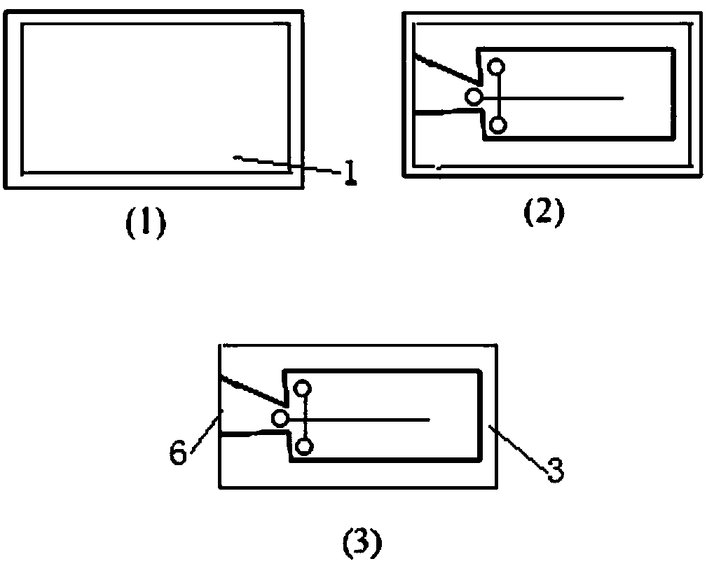
[0034] Step 1: Prepare a microfluidic chip template 3 by using the preparation method of a microfluidic chip template in Example 1.

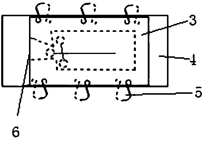
[0035] Step 2: If image 3 As shown, it includes the following steps: attaching the microfluidic chip template 3 to the plexiglass plate 4 to form an inner cavity, clamping and fixing the microfluidic chip template 3 and the plexiglass plate 4 with a clamp, and removing the PDMS prepolymer from the microfluidic chip The opening 6 on the fluidic chip template 3 is poured into the inner cavity, and the PDMS prepolymer is peeled off after curing to obtain a new microfluidic chip with exactly the same hole position and pipe length as the original prepared microfluidic chip 2. control chip 2.

[0036] When using the microfluidic chip 2 prepared by the microfluidic chip template 3 of the present invention, it is necessary to place a PDMS substrate under the prepared new microfluidic chip 2, so tha...


PUM


Abstract

The invention discloses a preparation method of a micro-fluidic chip template. The preparation method includes the steps: first, preparing a micro-fluidic chip; second, taking the micro-fluidic chip prepared in the first step as a model, and casting with AB polyester resin to prepare the micro-fluidic chip template. The invention further discloses the micro-fluidic chip template and an applicationthereof. The application includes the steps: attaching the micro-fluidic chip template onto an organic glass plate to form an inner cavity; fixing the micro-fluidic chip template and the organic glass plate, pouring PDMS (polydimethylsiloxane) prepolymer into the inner cavity; solidifying the PDMS prepolymer; performing stripping to obtain a micro-fluidic chip completely consistent with an initially prepared micro-fluidic chip. The preparation method is simple and low in cost and can be finished in a common laboratory, materials are easily obtained, the punch position and the pipeline lengthof the original micro-fluidic chip are completely copied, and the micro-fluidic chips are integrally formed and good in repeatability.

Description

technical field [0001] The invention belongs to the field of microfluidic chips, and in particular relates to a microfluidic chip template and a preparation method and application thereof. Background technique [0002] Since the early 1990s, Widmer and Manz and Widmer of the Ciba Geigy Analytical Laboratory in Switzerland first proposed the concept of the Miniaturized total analysis system, which was used as an analysis platform for a large number of drug screening and DNA sequencing. The microfluidic chip is the current hotspot in the micro-total analysis system, and it most embodies the idea of ​​transferring the functions of the analytical laboratory to the chip. In 2004, the cover article of American Business 2.0 magazine listed microfluidic chip as one of the seven technologies that "change the world". [0003] At present, the materials used to process microfluidic chips include glass, quartz, polymer materials, etc. Among them, elastic polydimethylsiloxane (PDMS) mate...

Claims


Application Information

Patent Timeline
IPC IPC(8): B01L3/00
CPCB01L3/5027B01L3/502707B01L2200/10B01L2300/0861B01L2300/0887B01L2300/12
Inventor 吴剑张叶江佳丽张海瑞张梦雨孙小敏
Owner 安徽中医药高等专科学校
Why Eureka
Try Eureka