Integrated joint module of compact robot and compact robot

A robot and compact technology, applied in the field of robots, can solve the problems of excessive size, poor bearing capacity and dynamic performance of the integrated joint module, and achieve the effects of good rigidity, high integration, and improved bearing capacity and rigidity.

Pending Publication Date: 2018-05-15
HEFEI HIT PRECISION TRANSMISSION CO LTD
View PDF8 Cites 7 Cited by
  • Summary
  • Abstract
  • Description
  • Claims
  • Application Information

AI Technical Summary

Problems solved by technology

[0004] The technical problem to be solved by the present invention is that the load capacity and dynamic performance of the current integrated joint module are poor, and the size is too long

Method used


Image

  • Integrated joint module of compact robot and compact robot
  • Integrated joint module of compact robot and compact robot

Examples


Embodiment 1

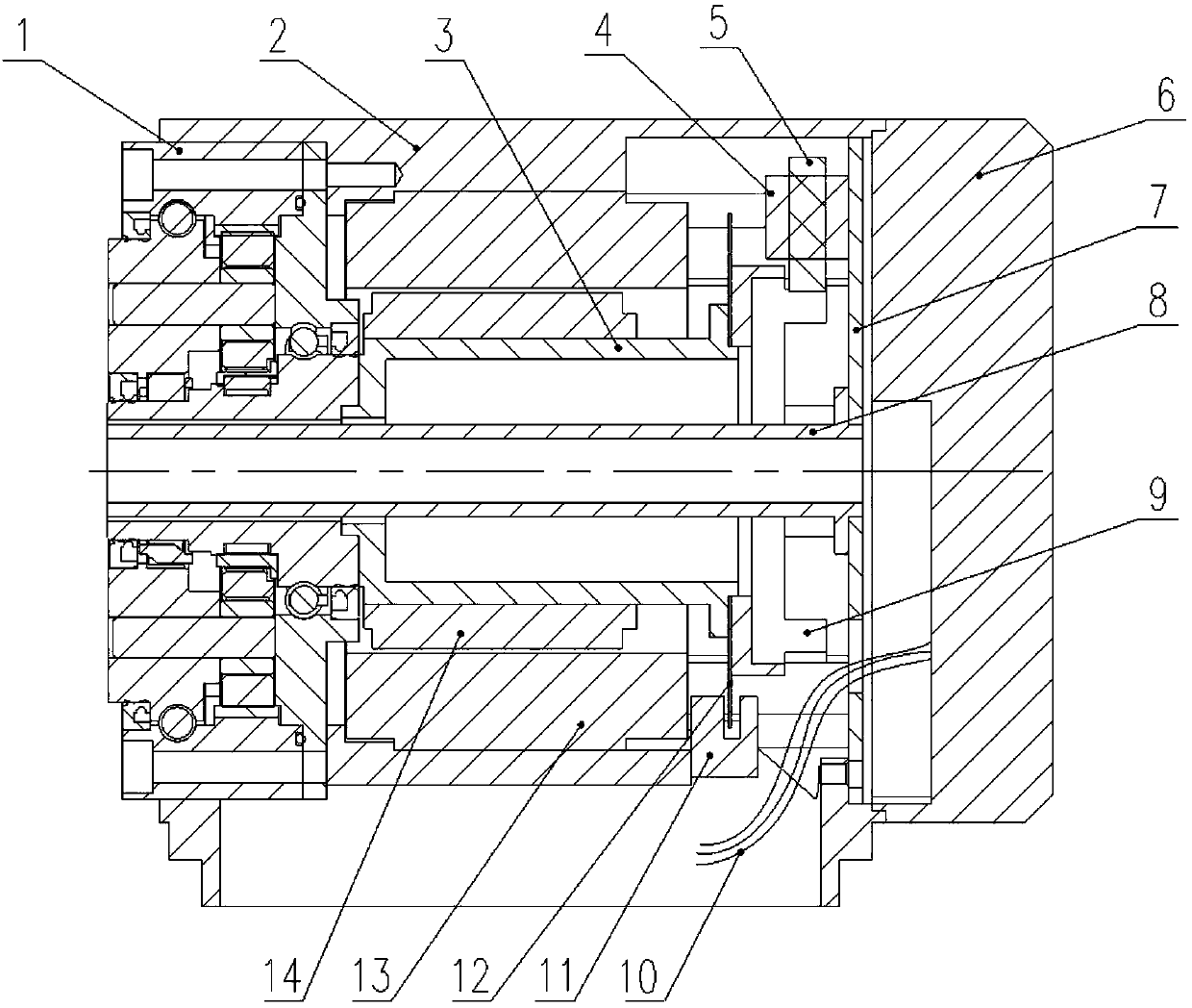
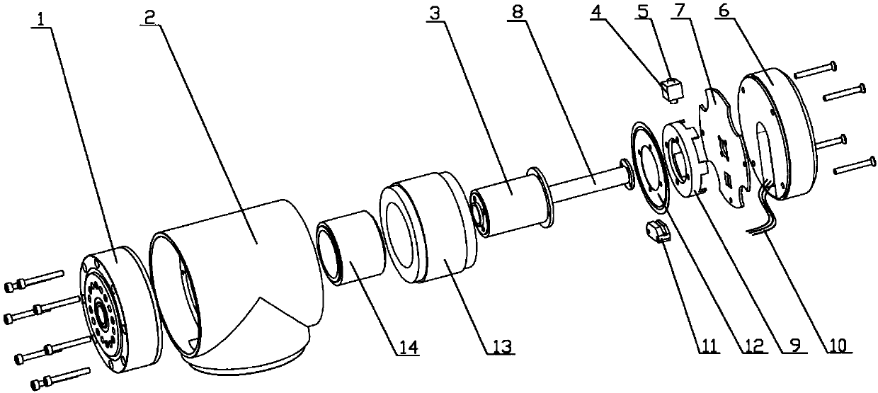
[0030] combined with figure 1 and figure 2 , a compact robot integrated joint module of the present invention, including a cycloidal pinwheel reducer 1, a housing 2, a shaft 3, an electromagnetic actuator 4, a movable pin 5, an integrated circuit module 6, an end cover 7, a wire Cable protection sleeve 8, claw brake disc 9, cable 10, photoelectric encoder read head 11, photoelectric encoder disc 12, motor stator 13 and motor rotor 14;

[0031] The cycloid reducer 1, the shaft 3, the photoelectric encoder disk 12, the motor stator 13 and the motor rotor 14 are coaxial;

[0032] The cycloidal pinwheel reducer 1 is fixed on the front end of the housing 2, the motor stator 13 is fixed in the housing 2, the motor rotor 14 is fixedly connected to the shaft 3, and the front end of the shaft 3 is decelerated with the cycloidal pinwheel The input end of the device 1 is fixedly connected, and the rear end of the shaft 3 is fixedly connected with the photoelectric encoder disc 12 and ...

Embodiment 2

[0035] combined with figure 1 and figure 2 , the difference from Embodiment 1 is that, further, it also includes a cable protective cover 8, the cycloidal pinwheel reducer 1 is a hollow structure, and the cable protective cover 8 runs through the cycloidal needle from front to back in sequence Wheel reducer 1, shaft 3 and end cover 7 are located inside cycloidal pinwheel reducer 1, shaft 3 and end cover 7, and the front end of cable protection sleeve 8 is fixedly connected with cycloidal pinwheel reducer 1 , the rear end is connected to the end cover 7, and the signal wires and power wires can pass through the cable protection sleeve 8 from the front end for wiring arrangement, which can protect the cables passing through the central hole of the integrated joint module.

Embodiment 3

[0037] combined with figure 1 and figure 2 , the difference from Embodiment 2 is that, further, the braking device includes an electromagnetic actuator 4, a movable pin 5 and a claw brake disc 9, and the claw brake disc is fixed on the rear end of the shaft 3 and is located on the photoelectric encoder disc 12, the electromagnetic actuator 4 is fixed on the end cover 7 and is located inside the housing 2, and the movable pin 5 is arranged on the electromagnetic actuator 4 and moves axially under the drive of the electromagnetic actuator 4. A circle of convex teeth is uniformly distributed along the axial direction on the circumference of the moving disk 9, and the movable pin 5 moves along the axis to insert into the convex teeth or retract.

[0038] The electromagnetic actuator 4 makes the moving pin 5 move along its own axis; when the electromagnetic actuator 4 eliminates the suction force, the moving pin 5 protrudes and gets stuck between the convex teeth of the claw brak...


PUM


Abstract

The invention provides an integrated joint module of a compact robot and the compact robot, and relates to the technical field of robots. The integrated joint module comprises a single cycloidal pin wheel speed reducer, a shell, a shaft, an electromagnetic actuator, a movable pin, an integrated circuit module, an end cover, a cable protection sleeve, a claw brake disc, a cable, a photoelectric encoder read head, a photoelectric encoding disc, a motor stator and a motor rotor. The single cycloidal pin wheel speed reducer is fixed to the front end of the shell, the motor stator is fixed in the shell, and the motor rotor is fixedly connected with the shaft. The front end of the shaft is fixedly connected with the input end of the single cycloidal pin wheel speed reducer. The rear end of the shaft is sequentially fixedly connected with the photoelectric encoding disc and a brake device. The photoelectric encoder read head is fixed in the shell and is opposite to the photoelectric encodingdisc in position, and the end cover is fixed to the rear end of the shell. The integrated joint module of the compact robot and the compact robot are high in integrity, small in size, large in load dead load ratio and good in rigidity, the structure is hollow, collision detection is conducted, and design, installation, usage and maintenance of the robot are easier and more convenient.

Description

technical field [0001] The invention relates to the technical field of robots, in particular to a compact robot integrated joint module and a compact robot. Background technique [0002] Collaborative robot is an important direction of robot development and an important component of human-machine collaborative work. Collaborative robots generally adopt a modular design, and the integrated joint module is its most important module. The versatility, load-to-weight ratio, and structural size of the integrated joint module greatly affect the performance and application fields of collaborative robots. [0003] The existing robot integrated joint module is usually composed of a harmonic reducer, a motor, a brake, a photoelectric encoder and a force sensor in series, and its axial dimension is long, and its load capacity and dynamic performance are limited. Contents of the invention [0004] The technical problem to be solved by the present invention is that the current integra...

Claims


Application Information

Patent Timeline
Patent Type & Authority Applications(China)
IPC IPC(8): B25J17/02B25J19/00
CPCB25J17/0258B25J19/0004B25J9/102B25J13/088B25J17/00
Inventor 王飞于振中丁亮李鹭扬王健
Owner HEFEI HIT PRECISION TRANSMISSION CO LTD
Why Eureka
Try Eureka