
Anti-leakage lubricating oil supply system of power device

A technology of supply system and power unit, applied in the direction of turbine/propulsion unit lubrication, engine lubrication, lubricating oil container, etc., can solve problems such as oil leakage, and achieve the effect of reducing operating cost, convenient operation and simple technical structure

Pending Publication Date: 2018-05-15
HARBIN ENG UNIV
View PDF13 Cites 7 Cited by
  • Summary
  • Abstract
  • Description
  • Claims
  • Application Information

AI Technical Summary

Problems solved by technology

[0006] To sum up, the methods to prevent leakage that have been seen so far are all containment methods. Whether it is using mechanical structure seals or using external air pressure, the design idea is to contain oil leakage.

Method used


Image

  • Anti-leakage lubricating oil supply system of power device

Examples


Embodiment approach 1

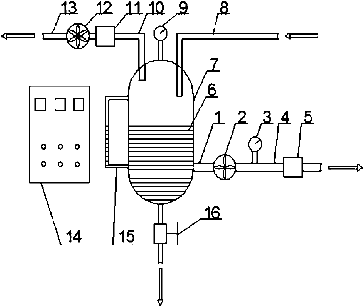
[0038] to combine figure 1 Describe this embodiment, a kind of anti-leakage lubricating oil supply system of a power plant (such as a gas turbine) in this embodiment, the anti-leakage lubricating oil supply system includes an oil supply pump inlet pipe 1, an oil supply pump 2, an oil supply pressure gauge 3, Oil pump outlet pipe 4, oil supply filter 5, lubricating oil 6, oil storage tank 7, equipment oil return pipe 8, oil storage tank pressure gauge 9, vacuum pump intake pipe 10, vacuum pump 12 and vacuum pump exhaust pipe 13; of which: The top of the oil storage tank 7 is provided with a vacuum pump intake pipe 10, the inlet end of the vacuum pump intake pipe 10 is inserted into the inside of the oil storage tank 7 from the top of the oil storage tank 7, and the outlet end of the vacuum pump intake pipe 10 is connected with the vacuum pump 12 intake ports, The outlet end of the vacuum pump 12 is connected with the vacuum pump exhaust pipe 13; the top of the oil storage tank ...

Embodiment approach 2

[0045] This embodiment adds a technical feature liquid level gauge 15 on the basis of Embodiment 1. The anti-leakage lubricating oil supply system of this embodiment also includes a liquid level gauge 15; connected.

[0046] The liquid level gauge 15 adopted in this embodiment can conveniently observe the liquid level height of the lubricating oil 6 in the oil storage tank 7 .

Embodiment approach 3

[0048] This embodiment is to increase the technical feature sewage pipe 16 on the basis of Embodiment 1 or 2. In this embodiment, the lowest part of the oil storage tank 7 is provided with a sewage pipe 16 that communicates with the inside of the oil storage tank 7; There is a drain valve on it.

[0049] In this embodiment, one end of the drain valve 16 communicates with the lowest position of the oil storage tank 7 , and the other end leads to the outside of the oil storage tank 7 .

[0050] In this embodiment, a sewage outlet is provided at the lowest part of the oil storage tank. After stopping for a period of time, part of the lubricating oil with impurities can be exhausted out of the oil storage tank through the sewage outlet. It is not necessary to replace all the lubricating oil, which can effectively reduce the loss of lubricating oil. .


PUM


Abstract

The invention discloses an anti-leakage lubricating oil supply system of a power device, and belongs to the technical field of mechanical and power equipment lubrication supply. The lubricating oil supply system comprises an oil supply pump oil inlet pipe, an oil supply pump, an oil supply pressure meter, an oil supply pump oil outlet pipe, an oil supply filter, lubricating oil, an oil storage tank, an equipment oil return pipe, an oil storage tank pressure meter, a vacuum pump air inlet pipe, a vacuum pump air inlet filter, a vacuum pump and a vacuum pump exhaust pipe. According to the system, the lubricating system conducts lubrication in the running manner of the negative pressure lower than the environment pressure, an inlet and an outlet of a lubricating oil pump are in negative pressure; during work, the lubricating oil pump conveys the lubricating oil to the lubricating part; through control the pressure of the vacuum pump and the oil pump, it is guaranteed that the pressure atthe lubricating part is lower than the outer pressure of the lubricating system, a small amount of gas flows into a sealing cavity from the exterior of the lubricating system, the lubricating oil is driven to flow in the equipment oil return pipe direction, and accordingly the purpose that lubricating oil is prevented from leaking outwards from a gap is achieved. The system is applicable to gas turbines or other high-speed rotation power machines.

Description

technical field [0001] The invention relates to an anti-leakage lubricating oil supply system of a power device, which belongs to the technical field of pressure lubrication supply of machinery and power equipment. Background technique [0002] In gas turbines or other power devices, the lubricating oil system is extremely important for the lubrication and cooling of mechanical devices (such as bearings). On the one hand, lubricating oil is used to lubricate the rotating parts to reduce mechanical friction and power loss. On the other hand, it needs to pass The lubricating oil takes away the heat generated by the friction pair and dissipates the heat through the lubricating oil cooler to prevent the bearing from being damaged due to excessive temperature caused by friction. Therefore, the pressure lubrication method of circulating oil supplied by the lubricating oil pump is usually used for lubrication and cooling, so as to provide sufficient oil quantity to lubricate and co...

Claims


Application Information

Patent Timeline
Patent Type & Authority Applications(China)
IPC IPC(8): F16N7/38F02C7/06
CPCF02C7/06F16N7/38F16N2210/16F16N2250/04F16N2270/60F16N29/00F16N19/003F16N35/00F16N2270/70F16N2210/02F16N7/385
Inventor 王松王忠义万雷孙涛栾一刚夏春雷
Owner HARBIN ENG UNIV
Learn More