Micro concave roller and micro concave roller coating method

A technology of gravure roll and running direction, which is applied to the device for coating liquid on the surface, coating, textile and paper making, etc., and can solve the problems such as poor coating effect

Inactive Publication Date: 2018-05-18
CHANGDE JINDE NEW MATERIAL TECH CO LTD
View PDF7 Cites 2 Cited by
  • Summary
  • Abstract
  • Description
  • Claims
  • Application Information

AI Technical Summary

Problems solved by technology

[0005] The purpose of this application is to provide a micro gravure roll and a coating met

Method used


Image

  • Micro concave roller and micro concave roller coating method
  • Micro concave roller and micro concave roller coating method
  • Micro concave roller and micro concave roller coating method

Examples


Embodiment Construction

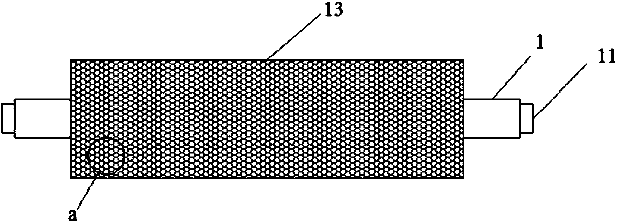
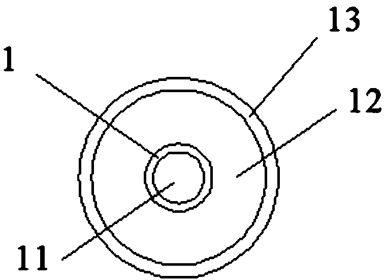
[0030] refer to Figure 1 to Figure 4 , a dimple roller according to the embodiment of the present application, including a main shaft 1;

[0031] Both ends of the main shaft 1 are fixed with bearing shafts 11;

[0032] A steel casing 12 is sheathed on the outside of the main shaft 1, and the length of the steel pipe casing 12 is shorter than the length of the main shaft 1;

[0033] The steel casing 12 is hard in texture, has a certain compressive capacity, and is not easy to be damaged during use or transportation.

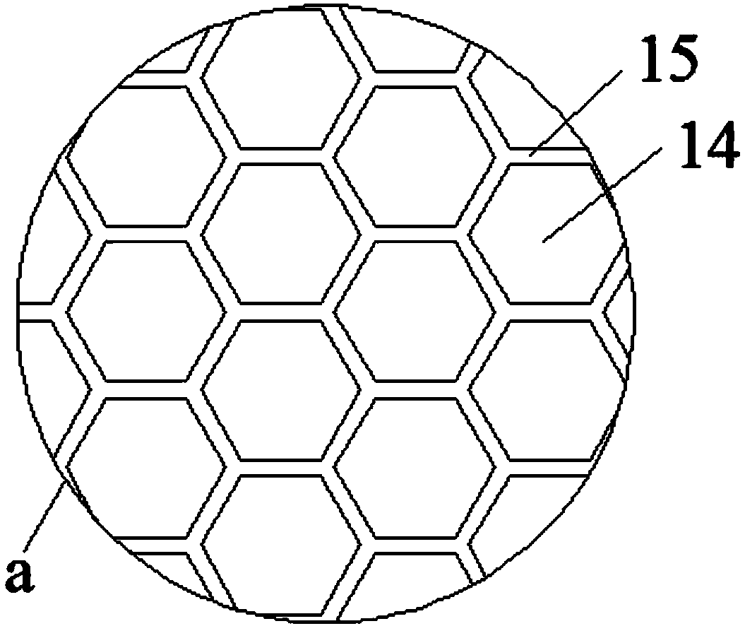
[0034] The axially outer surface of the steel casing 12 is covered with a hard ceramic tube 13;

[0035] The surface of the hard ceramic tube 13 is smooth and the friction force is small. When the paper is in contact with the hard ceramic tube 13, the damage to the paper can be reduced, thereby ensuring the quality of the product. In addition, ceramics have the advantages of almost no water absorption, high temperature resistance, corrosion resistance and wear...


PUM

PropertyMeasurementUnit
Diameteraaaaaaaaaa

Abstract

The invention discloses a micro concave roller and a micro concave roller coating method. the micro concave roller comprises a spindle, wherein bearing shafts are arranged at two ends of the spindle;a steel sleeve is arranged on the spindle in a sleeving manner; a hard ceramic tube is arranged on the outer surface of the steel sleeve in the axial direction in a sleeving manner; a plurality of hexagonal net holes are formed in the surface of the hard ceramic tube; the opening angle of each of the net holes is 60 degrees; the opening length is 133 microns; the depth of each of the net holes is33 microns; the net wall width of the micro concave roller is 8 microns; the line number of the micro concave roller is 180; and the diameter of the micro concave roller is 200-250 mm. The coating method comprises the following steps: adjusting the operating direction of paper and the micro concave roller, wherein the operating direction of the paper is opposite to that of the micro concave roller; and adjusting the operating speed of the paper and the micro concave roller, wherein the operating speed of the paper is less than that of the micro concave roller. According to the invention, the operating direction of the roller is changed; and the diameter of the microstructure of the micro concave roller are improved to enable the diameter of the micro concave roller is small and the material taking quantity of the micro concave roller to be large; and the moving direction of the micro concave roller is opposite to that of the paper, so that the relative speed of the paper and the microconcave roller is increased and the coating effect is improved.

Description

technical field [0001] The present application relates to the technical field of coating equipment, in particular to a micro-gravure roll and a coating method using the micro-gravity roll. Background technique [0002] Coating refers to the coating of pasty polymers, molten polymers or polymer melts on paper, cloth, and plastic films to make composite materials (films). The coating machine is mainly used for the surface coating process production of film, paper, etc. This machine is to coat the rolled substrate with a layer of glue, paint or ink with specific functions, and then wind it up after drying. [0003] Traditional coating equipment is usually equipped with upper and lower rollers, the upper roller is a rubber roller, and the lower roller is an anilox roller. The diameters of the two rollers are the same, and the two rollers are pressed together during coating. Because of the existence of pressing points, it is easy to produce wrinkles and broken lines, and the pap...

Claims


Application Information

Patent Timeline
IPC IPC(8): B05C1/08B05D1/28D21H23/58
CPCB05C1/0808B05C1/0826B05D1/28D21H23/58
Inventor 余赞彭宁罗臻钱正宇钟文田璐陈华杜建军
Owner CHANGDE JINDE NEW MATERIAL TECH CO LTD
Why Eureka
Try Eureka