Design method of heavy hammer piece progressive die

A design method and progressive die technology, applied in the direction of metal processing equipment, forming tools, manufacturing tools, etc., can solve the problems of large number of molds, low production efficiency, low efficiency, etc., to improve product precision, increase production efficiency, and achieve huge The effect of economic value

Inactive Publication Date: 2018-05-18
赵富祥
View PDF0 Cites 5 Cited by
  • Summary
  • Abstract
  • Description
  • Claims
  • Application Information

AI Technical Summary

Problems solved by technology

[0002] The original mold of the heavy hammer is stamped on a 40-ton punching machine using an ordinary composite mold. Due to the low efficiency in production, the number of molds invested is large, the labor intensity of the

Method used


Image

  • Design method of heavy hammer piece progressive die
  • Design method of heavy hammer piece progressive die
  • Design method of heavy hammer piece progressive die

Examples


Embodiment 1

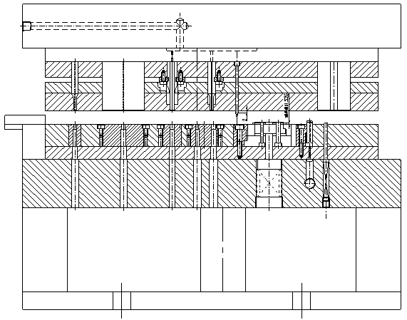
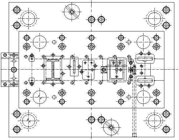
[0046]This embodiment provides a design method for the progressive die of the heavy hammer, which is characterized in that: the progressive die is designed as a single row of nine steps, that is, punching the process hole → guiding → trimming → punching grooves → punching three circles Hole → empty step → punching burr → embossing → drop shape; the working parts adopt a quick-change mosaic structure, which is convenient for processing, adjustment and replacement of inserts;

[0047] Due to the large output of parts and the high precision of the mold, in order to prevent the mold from deforming during use, the upper and lower mold base plates of the mold are all quenched and tempered with 45 steel; the concave plate is made of Cr12MoV mold steel, and the quenching hardness reaches 56-60HRC; other punches are fixed The plate, stripper plate and backing plate are all made of CrWMn die steel, with a quenching hardness of 56-58HRC; the punch and die inserts are made of wear-resistan...

Embodiment 2

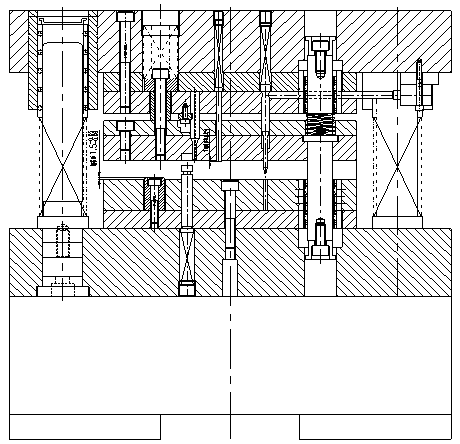
[0080] This embodiment provides a design method for the progressive die of the heavy hammer, which is characterized in that the progressive die is designed as a single row of nine steps, that is, punching the process hole → guiding → trimming → punching grooves → punching three circles Hole → empty step → punching burr → embossing → drop shape; the working parts adopt a quick-change mosaic structure, which is convenient for processing, adjustment and replacement of inserts;

[0081] Due to the large output of parts and the high precision of the mold, in order to prevent the deformation of the mold during use, the upper and lower mold seat plates of the mold are all quenched and tempered with 45 steel; the concave plate is made of Cr12MoV mold steel, and the quenching hardness reaches 56-60HRC; other punches are fixed The plate, stripper plate and backing plate are all made of CrWMn die steel with a quenching hardness of 56-58HRC; punches and die inserts are made of wear-resista...


PUM

PropertyMeasurementUnit
Quenching hardnessaaaaaaaaaa

Abstract

The invention discloses a design method of a heavy hammer piece progressive die. The progressive die is designed through single-row nine process steps, that is, process hole punching, guiding, edge cutting, groove punching, punching of three round holes, vacancy, burr punching, stamping, and shape forming. Working parts adopt quick-replacing-type splicing-inlaying structures, and machining, adjusting and replacing of inserts are facilitated. The part yield is large, the die precision is high, and thus in order to prevent deformation of the die in the using process, upper and lower die seat plates of the die both adopt 45 steel for thermal refining; a concave die plate adopts Cr12moV die steel, and the quenching hardness reaches 56-60 HRC; other punch fixing plates, unloading plates and thecushion plates all adopt CrWMn die steel, and the quenching hardness reaches 56-58 HRC; and punches and the concave die inserts adopt imported die steel DC53 with abrasion resistance and good toughness, and the quenching hardness reaches 60-63 HRC. The design method has the advantages that great economic value is created, the product precision is improved, the production efficiency is improved, and improvement of the quality of terminal products is guaranteed.

Description

technical field [0001] The invention relates to the field of die design, in particular to a design method of a heavy hammer progressive die. Background technique [0002] The original mold of the heavy hammer is stamped on a 40-ton punching machine using an ordinary composite mold. Due to the low efficiency in production, the number of molds invested is large, the labor intensity of the workers is high, and the size consistency of the parts is poor, and the mold management is troublesome. Replacement And maintenance is also frequent, the production efficiency is low, and the production demand cannot be met. Contents of the invention [0003] The purpose of the present invention is to improve production efficiency, and especially provides a design method of a heavy hammer piece progressive die. [0004] The invention provides a design method for a progressive die of a heavy hammer, which is characterized in that: the progressive die is designed as a single row of nine work...

Claims


Application Information

Patent Timeline
IPC IPC(8): B21D37/08B21D35/00B21D37/20B21D37/01
CPCB21D37/08B21D35/001B21D35/002B21D37/01B21D37/20
Inventor 赵富祥
Owner 赵富祥
Why Eureka
Try Eureka