Cutting device special for petroleum pipelines

A technology for cutting devices and oil pipelines, which is applied in the direction of pipe cutting devices, shearing devices, feeding devices, etc., and can solve the problem of affecting the cutting quality and scope of application of pipe cutting devices, affecting the connection of new pipe sections, sealing effect, and unable to ensure that the cuts are even. and other problems, to achieve the effect of sealing effect, neat cutting and reducing the use of manpower

Inactive Publication Date: 2018-05-18
CHENGDU DAMO PETROLEUM TECH CO LTD
View PDF8 Cites 2 Cited by
  • Summary
  • Abstract
  • Description
  • Claims
  • Application Information

AI Technical Summary

Problems solved by technology

With the continuous development of science and technology, the existing mechanized processing has been more and more widely used, so the corresponding mechanical cutting device is usually used to cut the oil pipeline, but because too many oil pipelines are laid in a relatively harsh environment During the process, leakage and rupture often occur. If the damage is too large to repair welding, it is necessary to cut off the damaged part and replace it with a new pipe. During the replacement process, it is necessary to ensure that the cut pipe is flat, but now In some procedures, one person surrounds the outer wall of the oil pipeline with a circle, and another person draws a line along the circle with a special stone pen, and then cuts along the drawn line. The problem with this method is that when When the pipe diameter is large, two people must operate at the same time to complete the line drawing work, which is a waste of manpower, and cutting according to the drawn line often cannot ensure that the cut is even, which affects the final connection and sealing effect with the new pipe section
Secondly, the pipe cutting needs to be turned manually for cutting, which consumes time and manpower, which greatly affects the cutting quality and scope of application of the pipe cutting device

Method used


Image

  • Cutting device special for petroleum pipelines
  • Cutting device special for petroleum pipelines
  • Cutting device special for petroleum pipelines

Examples


Embodiment

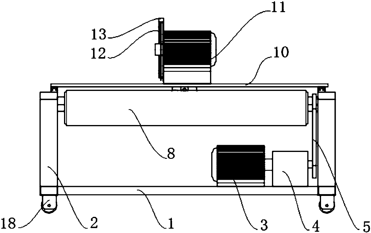
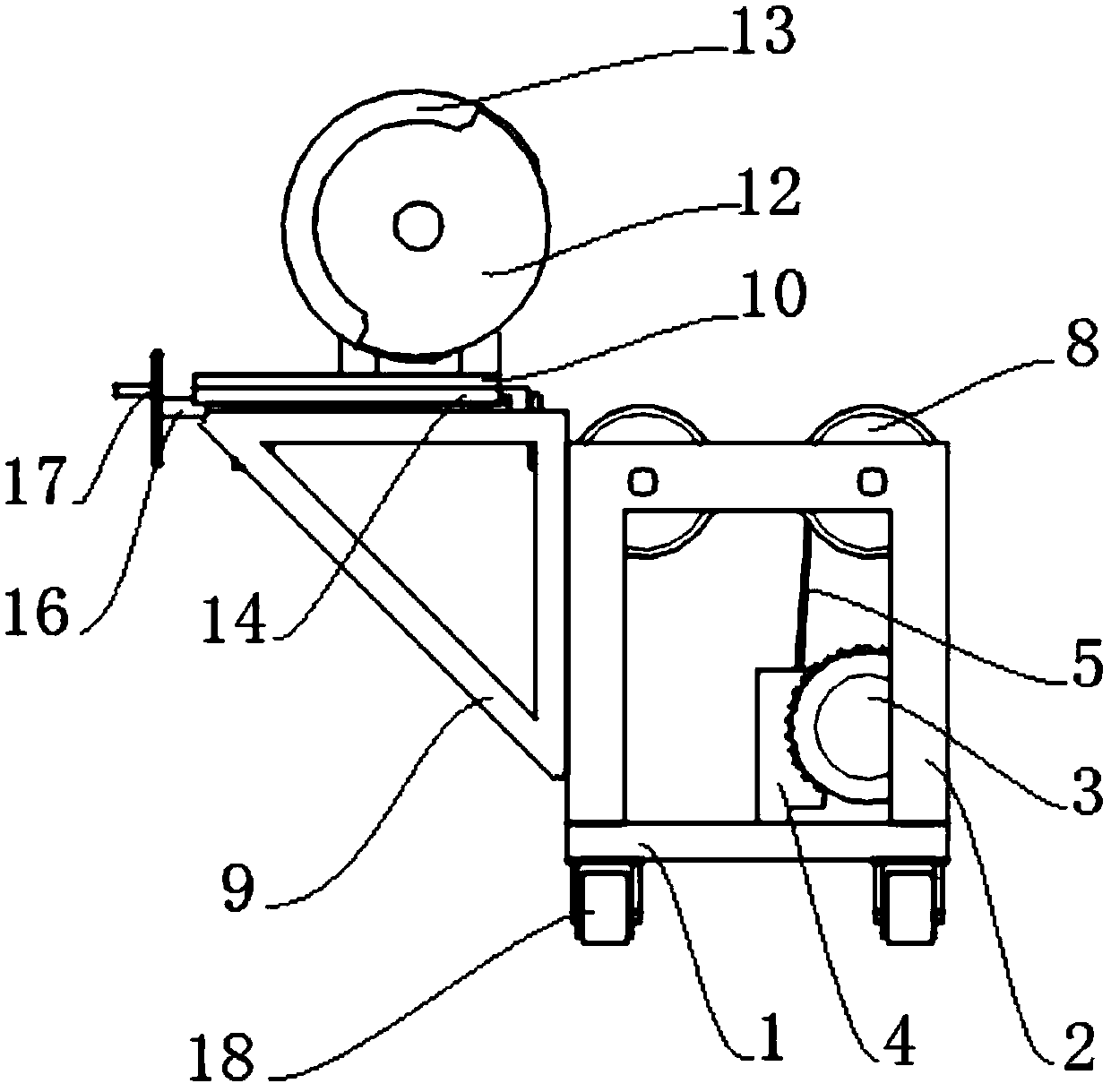
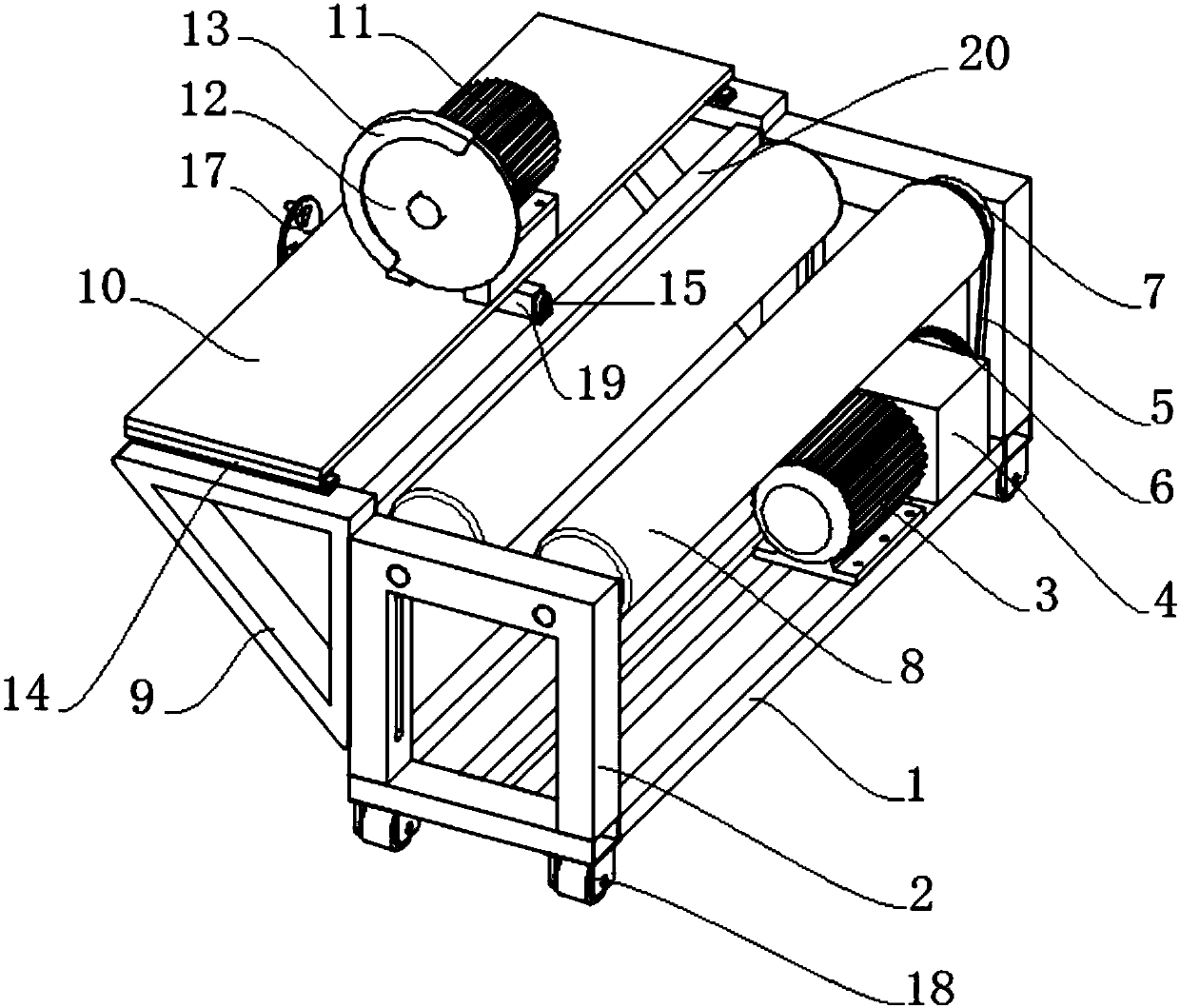
[0019] Such as Figure 1 to Figure 3 As shown, a cutting device dedicated to oil pipelines of the present invention includes a cutting device and a transmission unit, and the transmission unit includes a base 1, a bracket 2, a first motor 3, a reduction box 4, a transmission belt 5, and a first transmission pulley 6 , the second drive pulley 7, drive roller 8, two supports 2 are fixedly installed at the left and right ends of the base 1 respectively, and two drive rollers 8 are respectively installed at the top ends of the support 2, and the two drive rollers 8 are positioned at the same height and mutually Parallel, a second drive pulley 7 is fixedly installed on the shaft of any drive roller 8, the first motor 3 is connected with the reduction box 4 through a coupling, and the output shaft of the reduction box 4 is fixedly connected with the first drive pulley 6 , the first transmission pulley 6 and the second transmission pulley 7 are connected by a transmission belt 5, the...


PUM


Abstract

The invention discloses a cutting device special for petroleum pipelines. The cutting device comprises a cutting device body and a transmission unit. The transmission unit comprises a base, supports,a first electromotor, a reduction gearbox, a transmission belt, a first transmission belt wheel, a second transmission belt wheel and transmission rollers. The two supports are fixedly mounted at theleft end and the right end of the base correspondingly. The two transmission rollers are mounted at the two ends of the tops of the supports correspondingly. The second transmission belt wheel is fixedly mounted on a shaft rod of one transmission roller. The first electromotor is connected with the reduction gearbox through a coupling. An output shaft of the reduction gearbox is fixedly connectedwith the first transmission belt wheel. The first transmission belt wheel and the second transmission belt wheel are connected through a transmission belt. The first electromotor and the reduction gearbox are fixedly mounted on the base. A triangular frame is mounted on each support. An operation plate is mounted on the triangular frames. The cutting device body is fixedly mounted on the operationplate. According to the device, the petroleum pipelines of different pipe diameters can be cut, cutting is uniform, adopted manpower is reduced, the cutting quality is guaranteed, and the cutting efficiency is improved.

Description

technical field [0001] The invention relates to the technical field of petroleum equipment, in particular to a cutting device specially used for petroleum pipelines. Background technique [0002] In the oil industry, it is necessary to lay oil pipelines for oil transportation, and in the process of processing and laying oil pipelines, it is often necessary to cut the pipelines. With the continuous development of science and technology, the existing mechanized processing has been more and more widely used, so the corresponding mechanical cutting device is usually used to cut the oil pipeline, but because too many oil pipelines are laid in a relatively harsh environment During the process, leakage and rupture often occur. If the damage is too large to repair welding, it is necessary to cut off the damaged part and replace it with a new pipe. During the replacement process, it is necessary to ensure that the cut pipe is flat, but now In some procedures, one person surrounds th...

Claims


Application Information

Patent Timeline
Patent Type & Authority Applications(China)
IPC IPC(8): B23D21/00B23Q5/40B23Q7/00
CPCB23D21/00B23Q5/40B23Q7/00
Inventor 贺昶明
Owner CHENGDU DAMO PETROLEUM TECH CO LTD
Why Eureka
Try Eureka