Automatic profile cutting equipment

A technology for cutting equipment and profiles, which is applied in the field of automatic profile cutting equipment, can solve problems such as waste of resources, easy to generate rust, and profile shaking, and achieve the effects of increasing service life, low potential danger, and ensuring molding rate

Inactive Publication Date: 2018-05-18
钟丽菊
View PDF0 Cites 1 Cited by
  • Summary
  • Abstract
  • Description
  • Claims
  • Application Information

AI Technical Summary

Problems solved by technology

[0002] The CNC sawing machine is mainly used in the furniture industry and the cutting industry. The sawing machine uses circular saw blades, saw bands or saw blades as tools to saw metal round materials, square materials, pipe materials and profiles. It is mostly used in the material preparation workshop to cut various Bars, pipes and other profiles are driven by the driving wheel and the driven wheel to run the saw blade. The cutting direction of the saw blade is controlled by the guide rail control frame. The hydraulic cylinder piston rod supports the guide rail control frame to fall into the sawing material. The band sawing machine is equipped with a manual or hydraulic cylinder clamping and locking mechanism, and a hydraulic operation valve switch. When the existing CNC sawing machine cuts the profile, the clamping mechanism The clamping effect is relatively poor, the profile will shake when cutting, and the cutting will deviate, resulting in a low profile forming rate, wasting resources and increasing the cost of the enterprise, and it is impossible to lock profiles of different lengths. A large amount of iron filings are produced, which needs to be cleaned up in time. Due to the structure of the equipment, it is difficult to clean the main workpiece parts. The accumulation of iron filings will affect the normal use of the equipment. At the same time, the flying debris may cause injury to workers when cutting profiles. , the cutting tool on the existing CNC sawing machine is prone to rust after long-term use. When the tool needs to be replaced, it needs to be stopped for replacement, which is time-consuming and labor-intensive, which affects the production efficiency of profile processing and has a certain impact on the enterprise.

Method used


Image

  • Automatic profile cutting equipment
  • Automatic profile cutting equipment
  • Automatic profile cutting equipment

Examples


Embodiment Construction

[0015] The following will clearly and completely describe the technical solutions in the embodiments of the present invention with reference to the accompanying drawings in the embodiments of the present invention. Obviously, the described embodiments are only some, not all, embodiments of the present invention. Based on the embodiments of the present invention, all other embodiments obtained by persons of ordinary skill in the art without making creative efforts belong to the protection scope of the present invention.

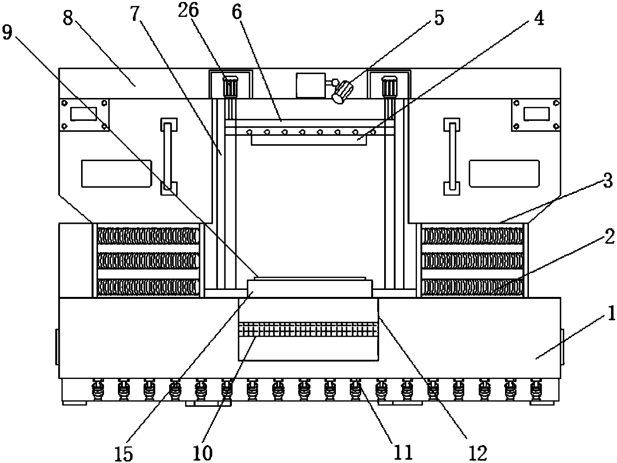
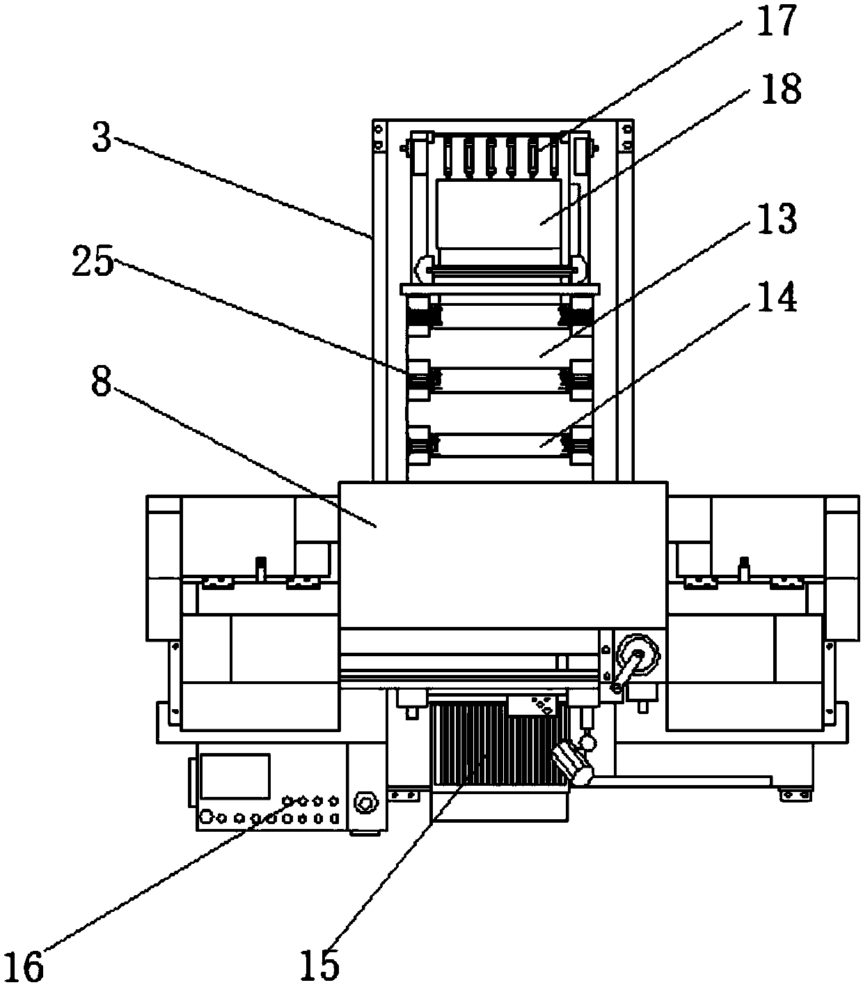
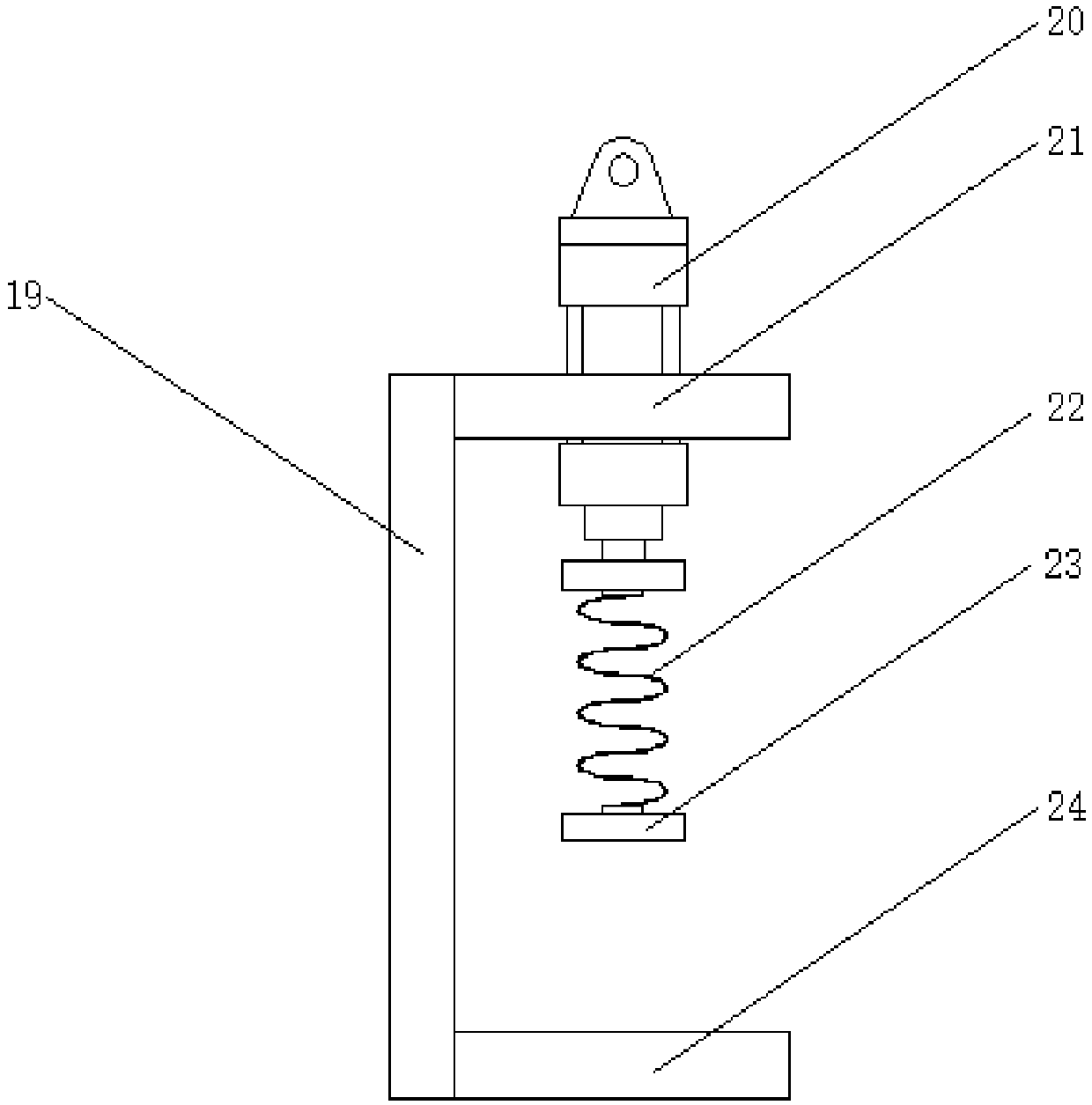
[0016] see Figure 1-3 , an embodiment provided by the present invention: a profile automatic cutting equipment, including a base 1, a column 7, a mounting plate 8, a workbench 9 and a conveyor belt 13, a group of columns 7 are symmetrically arranged at the middle position of the top of the base 1, and the columns The top of 7 is equipped with mounting plate 8, and the middle position of the inner bottom of mounting plate 8 is symmetrically provided with secon...


PUM


Abstract

The invention discloses automatic profile cutting equipment. The automatic profile cutting equipment comprises a base, a stand column, a mounting plate, a workbench and a conveying belt. The conveyingbelt is evenly provided with profile placement positions. First telescopic motors are symmetrically mounted on the two sides of the profile placement positions. Fixing plates are mounted at the output ends of the first telescopic motors. Upper fixing bases are mounted on the sides, away from the upper portions of the output ends of the first telescopic motors, of the fixing plates. Second pneumatic cylinders are mounted in the middles of the upper fixing bases. Limiting springs are arranged at the output ends of the second pneumatic cylinders. Positioning plates are arranged at the bottoms ofthe limiting springs. Lower fixing bases are mounted on the sides, away from the lower portions of the output ends of the first telescopic motors, of the fixing plates. The automatic profile cuttingequipment is provided with the upper fixing bases, the lower fixing bases, the second pneumatic cylinders, the fixing plates, the limiting springs and positioning blocks which form a clamping mechanism jointly, profiles with different widths can be clamped, the clamping effect is better, and the shape rate of the machined profiles is ensured.

Description

technical field [0001] The invention relates to the technical field of mechanical cutting, in particular to automatic cutting equipment for profiles. Background technique [0002] The CNC sawing machine is mainly used in the furniture industry and the cutting industry. The sawing machine uses circular saw blades, saw bands or saw blades as tools to saw metal round materials, square materials, pipe materials and profiles. It is mostly used in the material preparation workshop to cut various Bars, pipes and other profiles are driven by the driving wheel and the driven wheel to run the saw blade. The cutting direction of the saw blade is controlled by the guide rail control frame. The hydraulic cylinder piston rod supports the guide rail control frame to fall into the sawing material. The band sawing machine is equipped with a manual or hydraulic cylinder clamping and locking mechanism, and a hydraulic operation valve switch. When the existing CNC sawing machine cuts the profil...

Claims


Application Information

Patent Timeline
Patent Type & Authority Applications(China)
IPC IPC(8): B23D51/02B23D51/04B23Q11/00
CPCB23D51/02B23D51/04B23Q11/0064
Inventor 钟丽菊
Owner 钟丽菊
Why Eureka
Try Eureka