
Device and method for continuously preparing optical fiber preform rods and achieving drawing

An optical fiber preform and preform technology, which is applied to glass fiber drawing devices, glass manufacturing equipment, manufacturing tools, etc., can solve the problems of large differences in product parameters, generation of tapered waste, and increase in production costs, so as to improve the utilization of raw materials. The effect of high rate and product quality

Pending Publication Date: 2018-05-18
TONGDING INTERCONNECTION INFORMATION CO LTD +1
View PDF10 Cites 5 Cited by
  • Summary
  • Abstract
  • Description
  • Claims
  • Application Information

AI Technical Summary

Problems solved by technology

[0008] In summary, according to the existing process of preparing optical fiber preform and drawing process, there are the following disadvantages: (1) A large number of auxiliary materials need to be used in the process of making rod and drawing, and it is necessary to align the core Pickling or polishing process for the rod or prefabricated rod greatly increases the production cost; (2) In the process of wire drawing and rod making, cone waste will be generated at the head and tail of the rod, which reduces the utilization rate of the rod and raw materials ; (3) Since wire drawing and preform preparation are all carried out individually one by one, the process stability and continuity are poor, and the difference in product parameters is also large

Method used


Image

  • Device and method for continuously preparing optical fiber preform rods and achieving drawing

Examples


Embodiment Construction

[0033] It should be noted that, in the case of no conflict, the embodiments of the present invention and the features in the embodiments can be combined with each other.

[0034] In describing the present invention, it should be understood that the terms "center", "longitudinal", "transverse", "upper", "lower", "front", "rear", "left", "right", The orientations or positional relationships indicated by "vertical", "horizontal", "top", "bottom", "inner", "outer", etc. are based on the orientation or positional relationships shown in the drawings, and are only for the convenience of describing the present invention Creation and simplification of description, rather than indicating or implying that the device or element referred to must have a specific orientation, be constructed and operate in a specific orientation, and therefore should not be construed as limiting the invention. In addition, the terms "first", "second", etc. are used for descriptive purposes only, and should no...


PUM


Abstract

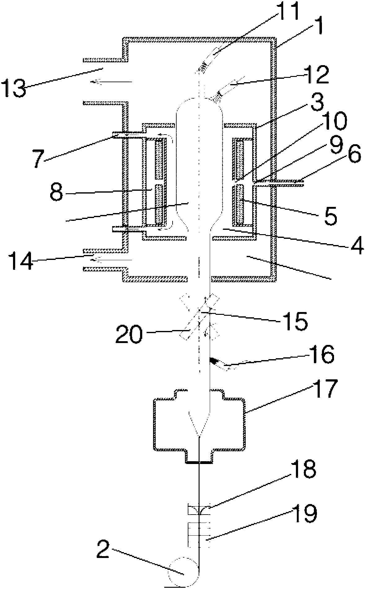
The invention provides a device for continuously preparing optical fiber preform rods and achieving drawing. The device comprises a preform rod preparation unit and a drawing furnace, the preform rodpreparation unit is internally provided with a degassing sintering unit, and the degassing sintering unit comprises heating devices arranged in a degassing sintering cavity of the degassing sinteringunit; a core-layer blow torch and a covering-layer blow torch are arranged above the degassing sintering unit; the preform rod preparation unit is provided with an upper tail gas exhaust pipe, and thelower portion of a deposition chamber is correspondingly provided with a lower exhaust pipe; a driving mechanism, a flame polishing device, the drawing furnace, a coating device, a curing device anda traction wheel are sequentially arranged below the preform rod preparation unit. According to the device, by specially designing a blow torch system, a preform rod motion system and the like of theoptical fiber preform rods, the optical fiber preform rods can be continuously prepared, and meanwhile the prepared optical fiber preform rods are drawn into optical fibers online.

Description

technical field [0001] The invention belongs to the technical field of optical fiber preform production and manufacturing, and in particular relates to a device and method for continuously preparing and drawing optical fiber preforms. Background technique [0002] At present, the preparation of optical fiber preform and fiber drawing are two independent processes, that is, the finished preform is prepared in the optical fiber preform workshop or company, and then sent to the optical fiber drawing workshop or company to be drawn into optical fiber. Optical fiber preform is the most important and critical raw material in the fiber drawing process, which consists of a core rod and an outer cladding. From the perspective of the drawing process, the optical fiber preform can be divided into three categories according to the combination of the core rod and the outer cladding: solid rod, RIC rod (Rod inCylinder) and quartz sand online cladding rod. Quartz sand on-line cladding rod...

Claims


Application Information

Patent Timeline
IPC IPC(8): C03B37/014C03B37/025C03C25/12C03C25/104
CPCC03B37/0142C03B37/01446C03B37/025C03C25/104C03C25/12C03B2207/60C03B37/01406C03B37/0146C03B37/027C03B2205/30
Inventor 沈小平向德成王祥崔德运王兵钦梁伟刘建中何炳满小忠朱坤
Owner TONGDING INTERCONNECTION INFORMATION CO LTD
Learn More