Primary throttling low-temperature refrigeration system pre-cooled by utilizing the vortex tube energy separation effect

A technology of energy separation and vortex tube, which is applied in refrigerators, refrigeration components, refrigeration and liquefaction, etc., can solve the problems of limited pre-cooling effect and large compressor pressure ratio, and achieve simple structure, low refrigeration temperature and pre-cooling effect Good results

Active Publication Date: 2018-05-18
NINGBO INST OF TECH ZHEJIANG UNIV ZHEJIANG
View PDF4 Cites 0 Cited by
  • Summary
  • Abstract
  • Description
  • Claims
  • Application Information

AI Technical Summary

Problems solved by technology

[0004] However, the existing once throttling low-temperature refrigeration system still has the following technical problems: the direct use of the throttling low-temperature and low-pressure precooling gas needs to pass through the regenerator 2a, th

Method used


Image

  • Primary throttling low-temperature refrigeration system pre-cooled by utilizing the vortex tube energy separation effect
  • Primary throttling low-temperature refrigeration system pre-cooled by utilizing the vortex tube energy separation effect
  • Primary throttling low-temperature refrigeration system pre-cooled by utilizing the vortex tube energy separation effect

Examples


Embodiment 1

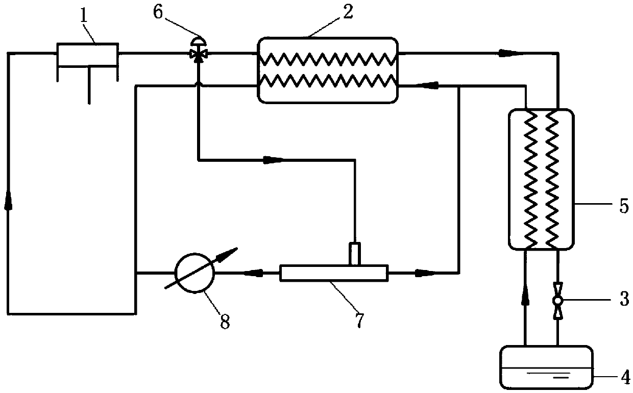
[0020] A throttling low-temperature refrigeration system for precooling using the energy separation effect of a vortex tube, comprising a compressor 1, a regenerator, a throttle valve, an evaporator 4, and a radiator 8, and the regenerator includes a first regenerator 2 and the second regenerator 5, further comprising a three-way flow regulating valve 6 and a vortex tube 7, the outlet of the compressor 1 communicates with the inlet of the three-way flow regulating valve 6, and the three-way flow regulating valve 6 The first outlet communicates with the inlet of the hot end of the first regenerator 2, the second outlet communicates with the inlet of the vortex tube 7, and the outlet of the cold end of the first regenerator 2 communicates with the hot end of the second regenerator 5. The outlet of the cold end of the second regenerator 5 is connected in series with the throttle valve 3 and then connected with the inlet of the evaporator 4, and the outlet of the evaporator 4 is co...

Embodiment 2

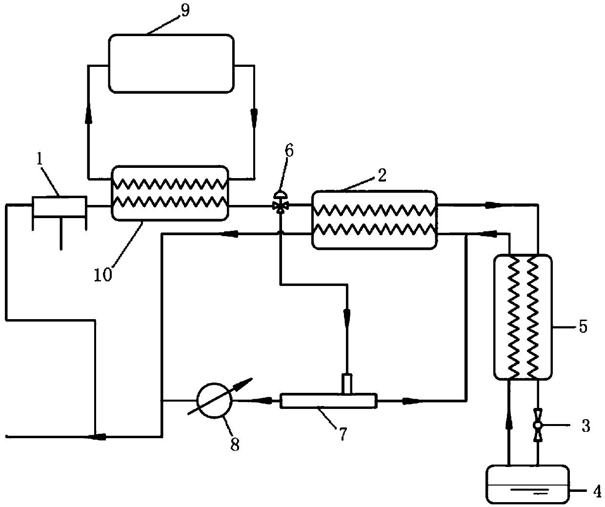
[0025] In this embodiment, on the basis of Embodiment 1, an external precooling device 9 and a third regenerator 10 are added, and the third regenerator 10 is arranged at the outlet of the compressor 1 and the inlet of the three-way flow regulating valve 6 Between, the inlet of the hot end of the third regenerator 10 is connected with the outlet of the compressor 1, the outlet of the cold end is connected with the inlet of the three-way flow regulating valve 6, and the cold end of the third regenerator 10 The inlet and the outlet of the hot end are respectively connected in series with the external precooling device 9 to form an external precooling circulation channel. This setting can perform rapid external pre-cooling on the high-pressure gas coming out of the compressor 1, so that the pre-cooling efficiency is higher.


PUM


Abstract

The invention discloses a primary throttling low-temperature refrigeration system pre-cooled by utilizing the vortex tube energy separation effect. The system comprises a compressor, heat regenerators, a throttling valve and an evaporator, and is characterized in that the heat regenerator comprises a first heat regenerator and a second heat regenerator; the system further comprises a three-way flow regulating valve and a vortex tube; an outlet of the compressor communicates with an inlet of the three-way flow regulating valve, a first outlet of the three-way flow regulating valve communicateswith a hot end inlet of the first heat regenerator, and a second outlet of the three-way flow regulating valve communicates with an inlet of the vortex tube; a cold end outlet of the vortex tube and ahot end outlet of the second heat regenerator are combined into one path to communicate with a cold end inlet of the first heat regenerator; and a hot end outlet of the first heat regenerator communicates with an inlet of the compressor. The primary throttling low-temperature refrigeration system pre-cooled by utilizing the vortex tube energy separation effect has the advantages that structure issimple, internal pre-cooling can be adopted, and the refrigerating efficiency is high.

Description

technical field [0001] The invention relates to the technical field of low-temperature refrigeration, in particular to a throttling low-temperature refrigeration system for precooling by utilizing the energy separation effect of a vortex tube. Background technique [0002] With the development of science and technology, the application range and demand of small cryogenic refrigerators in different fields are becoming wider and wider, such as aerospace, national defense and military industry, low-temperature superconductivity, medical equipment, and transportation. According to different refrigeration methods, the currently widely used small cryogenic refrigerators can be divided into many different types, such as throttling refrigerators, GM refrigerators, Stirling refrigerators, and pulse tube refrigerators. Among them, throttling refrigeration technology is the earliest developed and applied mature refrigeration technology in low temperature refrigeration technology. effe...

Claims


Application Information

Patent Timeline
IPC IPC(8): F25B9/04F25B40/06F25B41/06F25B41/30
CPCF25B9/04F25B40/06F25B41/31
Inventor 陈光明黎念高能宣永梅
Owner NINGBO INST OF TECH ZHEJIANG UNIV ZHEJIANG
Why Eureka
Try Eureka