Telephone receiver and assembly method thereof

A receiver and free technology, applied in the field of receivers, can solve the problems of complex structure and poor sensitivity of moving iron receivers, and achieve the effects of reducing vibration response time, improving sensitivity, and simplifying the overall structure

Pending Publication Date: 2018-05-18
SUZHOU YICHUAN TECH CO LTD
View PDF0 Cites 3 Cited by
  • Summary
  • Abstract
  • Description
  • Claims
  • Application Information

AI Technical Summary

Problems solved by technology

[0006] Therefore, the technical problem to be solved by the present invention is to overcome the problems of complex structure and poor sensitivity of the moving iron receiver in the prior art

Method used


Image

  • Telephone receiver and assembly method thereof
  • Telephone receiver and assembly method thereof
  • Telephone receiver and assembly method thereof

Examples


Embodiment 1

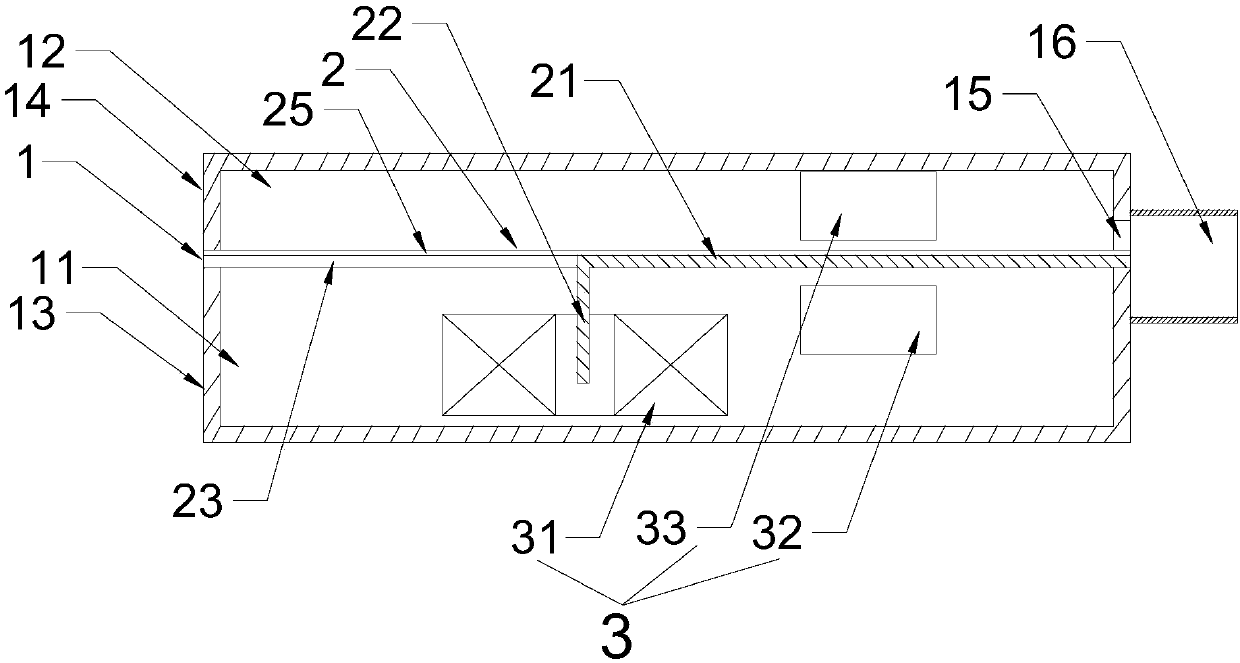
[0065] This embodiment provides a receiver, such as figure 1 As shown, it includes a housing 1 , a diaphragm mechanism 2 and an electromagnetic mechanism 3 .

[0066] The casing 1 includes a first housing 13 surrounded by a first bottom surface and side walls, and a second housing 14 surrounded by a second bottom surface and side walls. The openings of the first housing 13 and the second housing 14 are buckled Together to form a hollow cavity. Both the first housing 13 and the second housing 14 are made of high magnetic permeability alloy, and the side wall of the second housing 14 is provided with a sound hole 15, and the periphery of the sound hole 15 is provided with a sound guide tube 16, The sound guide tube 16 is arranged on the side wall of the housing 1 .

[0067] It should be noted that the installation between the first housing 13 and the second housing 14 is detachable, and the setting position of the sound hole 15 is not limited, and it can also be arranged on th...

Embodiment 2

[0090] This embodiment provides a receiver, which differs from the receiver provided in Embodiment 1 in that the structure of the diaphragm mechanism 2 is different.

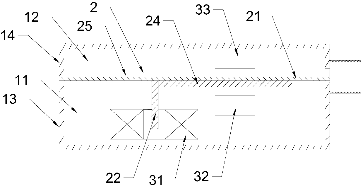
[0091] Such as image 3 As shown, the diaphragm mechanism 2 includes a fixed frame 23, a sounding diaphragm 25 and a vibrating body.

[0092] The structure of the fixing frame 23 is the same as the fixing frame 23 of the receiver provided in Embodiment 1, and will not be repeated here.

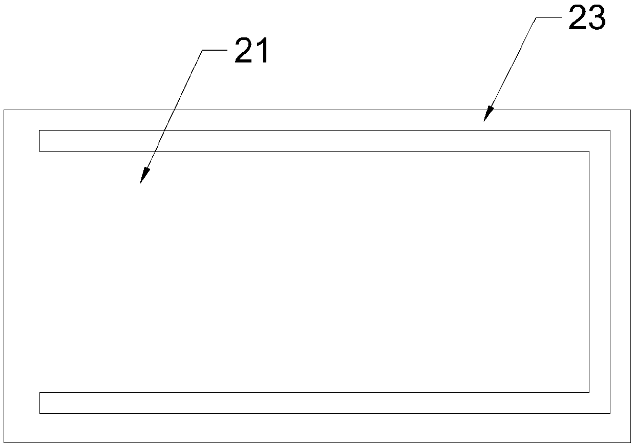
[0093] The vibrating body includes a vibrating plate, a free part 22 and a connecting part 24 . Such as figure 2 As shown, the vibrating plate is used as the vibrating part 21 of the vibrating body, which is made of soft magnetic material, one end is fixed on the fixed frame 23 , and the other end is suspended in the inner cavity of the fixed frame 23 . It should be noted that the vibrating plate is not bent, but suspended in the cavity of the fixed frame 23 as a whole.

[0094] The free part 22 and the connecting part 24 a...

Embodiment 3

[0103] This embodiment provides a receiver. Compared with any receiver provided in Embodiment 1 or Embodiment 2, the difference lies in that the fixing positions of the fixing frame 23 are different.

[0104] In this embodiment, the outer edge of the fixing frame 23 in the diaphragm mechanism 2 is fixed on the inner wall surface of the second casing 14 .

[0105] The difference between the assembly method (abbreviated as C assembly method) and A assembly method or B assembly method of receiver in the present embodiment is:

[0106] In step S20, the outer edge of the fixed frame 23 in the diaphragm mechanism 2 is fixed on the inner wall surface of the second housing 14, and the second magnetic generating element 33 is avoided;

[0107] In step S30, the opening of the second housing 14 is buckled at the opening of the first housing 13, and the first magnetic generating member 32 in the first housing 13 is connected to the second magnetic generating member 32 in the second housin...


PUM


Abstract

The invention discloses a telephone receiver and an assembly method thereof. The telephone receiver comprises a housing, a vibrating diaphragm mechanism and an electromagnetic mechanism; the vibratingdiaphragm mechanism is provided with a vibrating portion having at least one end fixed on the housing, and a free portion connected with the vibrating portion and stretched into a first cavity; and under the action of an electromagnetic field generated after a coil is powered on and a fixed magnetic field generated by a first magnetic generation piece, the free portion and the vibrating portion are driven to vibrate reciprocally. The assembly method comprises the steps of fixing a first magnetic generation piece on an inner wall of a first housing and fixing a coil on the inner wall of the first housing; fixing a vibrating diaphragm mechanism on an opening of the first housing so that a free portion is stretched into the coil; and buckling an opening of a second housing on the opening ofthe first housing. According to the telephone receiver provided by the invention, only one integral vibrating diaphragm mechanism needs to be provided, so an integral structure of the telephone receiver is simplified, a vibration response time is greatly reduced and the sensitivity of the telephone receiver is improved; and moreover, the vibrating diaphragm mechanism is installed integrally, so the assembly difficulty is greatly reduced.

Description

technical field [0001] The invention relates to the technical field of receivers, in particular to a receiver and an assembly method thereof. Background technique [0002] The receiver is a tiny electro-acoustic device that converts audio electrical signals into sound signals without sound leakage, so as to realize audio playback. It is widely used in portable electronic equipment such as mobile phones, notebook computers, earphones, and hearing aids. [0003] According to the working principle, receivers can be divided into moving coil type, electromagnetic type (moving iron type), piezoelectric type, carbon particle type, etc. Among them, moving iron type receivers are widely used because of their stable frequency response curve and high sensitivity. The working principle of the moving iron receiver is electromagnetic energy conversion, that is, the sound is transmitted to the electromagnetic coil in the form of an alternating current signal, and the electromagnetic coil g...

Claims


Application Information

Patent Timeline
Patent Type & Authority Applications(China)
IPC IPC(8): H04R11/04H04R31/00
CPCH04R11/04H04R31/003H04R2231/001H04R2410/00
Inventor 陈晓明吴哲
Owner SUZHOU YICHUAN TECH CO LTD
Why Eureka
Try Eureka