Method for determining axial compression stability bearing capacity of double-limb compound section column of dust collector box
A technology of stable bearing capacity and combined cross-section, which is applied in the direction of instruments, electrostatic separation covers, electrical digital data processing, etc., to achieve the effects of wide application range, convenient use and good reliability
- Summary
- Abstract
- Description
- Claims
- Application Information
AI Technical Summary
Problems solved by technology
Method used
Image
Examples
Embodiment 1
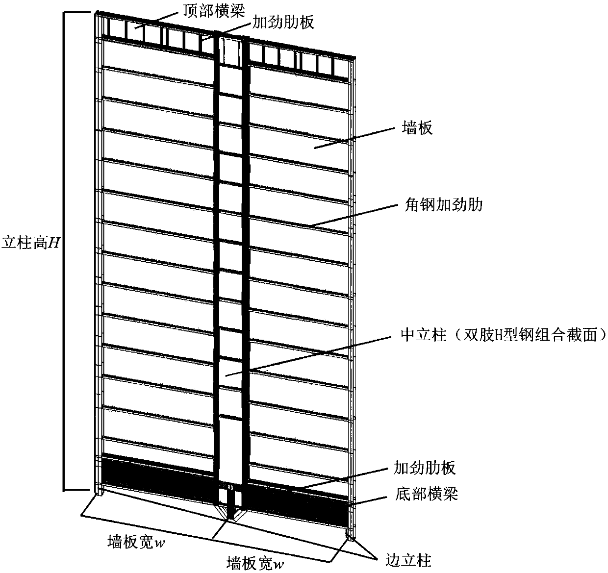
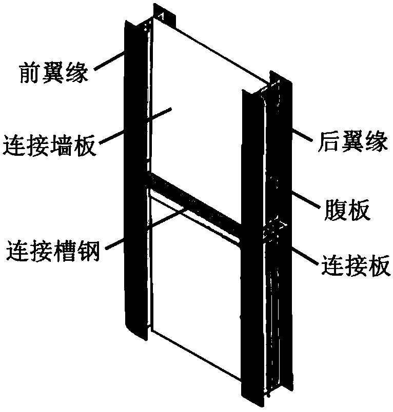
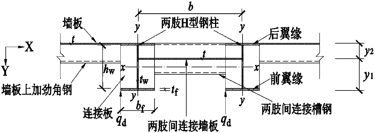
[0031] In the present invention, under the condition of considering the influence of the initial defects of the structure, the calculation, comparison and analysis of the axially stable bearing capacity of the double-leg combined section column in the dust collector structure with different geometric structures are numerically simulated through the finite element software ANSYS, and the stiffening wall of the dust collector The structural system of the slab-double-leg combined section column is shown in Figure 1, and the cross-sectional form of the double-leg combined column is shown in the attached figure 2 shown. In engineering practice, because the edge columns generally bear a small load and the design section is small, only the middle column in the calculation model is a double-leg composite section column, and the edge columns on both sides are single-leg hot-rolled H-shaped steel columns. The finite element calculation and analysis process is described as follows:
[0...
Embodiment 1
[0040] The column section of the dust collector box is H294×200×8×12 (section height h×flange width b f × web thickness t w × Flange thickness t f ), the thickness t of the wallboard and the connecting wallboard is 6mm, the width b of the connecting wallboard is 1120mm, and the distance between lateral supports is l 0 is 3100mm, and the middle surface of the connecting wallboard is located on the x-x axis of the symmetry axis of the H-shaped steel section, that is, y 1 (the distance between the middle surface of the connecting wall panel and the front flange) = y 2 (the distance between the middle surface of the connecting wall panel and the rear flange) = 147mm (if the model used in the follow-up analysis does not specify the position of the connecting wall panel, that is, according to y 1 =y 2 =0.5h value).
Embodiment 2
[0042] The section of the column of the dust collector box is H300×300×10×15 (mm), the thickness t of the wallboard and the connecting wallboard is 5mm, the width b of the connecting wallboard is 1320mm, and the distance between the lateral supports is l 0 It is 3700mm.
[0043] When the maximum axial residual stress σ is produced on the section of Example 1 rs,z,max up to 0.78f y , the axial residual stress distribution of the left leg H-shaped steel section near the top of the column (where the maximum axial compressive residual stress occurs in the section) is shown in the attached Figure 4(a) ~ Figure 4(d) As shown, the tensile stress is positive and the compressive stress is negative. Attached Figure 4(a) shows that the joints between the H-shaped steel web and the connecting wall plate, and the joint between the H-shaped steel rear flange and the wall plate generate residual tensile stress, and the residual tensile stress value decays quickly. The residual tensile st...
PUM
| Property | Measurement | Unit |
|---|---|---|
| Yield strength | aaaaa | aaaaa |
| Elastic modulus | aaaaa | aaaaa |
Abstract
Description
Claims
Application Information
 - R&D
- Intellectual Property
- Life Sciences
- Materials
- Tech Scout
- Unparalleled Data Quality
- Higher Quality Content
- 60% Fewer Hallucinations
Browse by: Latest US Patents, China's latest patents, Technical Efficacy Thesaurus, Application Domain, Technology Topic, Popular Technical Reports.
© 2025 PatSnap. All rights reserved.Legal|Privacy policy|Modern Slavery Act Transparency Statement|Sitemap|About US| Contact US: help@patsnap.com


