
flux transformer

A technology of magnetic flux converter and permanent magnet, applied in the direction of protection switch operation/release mechanism, etc., can solve the problems of non-uniform magnetic conductive material, reduced magnetic performance of permanent magnet, malfunction of intelligent circuit breaker, etc., to improve the utilization rate, The effect of reducing magnetic flux leakage and fast tripping

Active Publication Date: 2019-09-20
ZHEJIANG CHINT ELECTRIC CO LTD
View PDF4 Cites 0 Cited by
  • Summary
  • Abstract
  • Description
  • Claims
  • Application Information

AI Technical Summary

Problems solved by technology

The path of the magnetic force line in the direction of the core axis is long, the magnetic force line is easy to pass through the air and enter the casing, there is a lot of magnetic flux leakage, and the magnetic permeable material cannot work uniformly near the inflection point of the magnetization curve
[0005] Moreover, when the existing magnetic flux converter is energized, the electromagnetic field lines generated are opposite to the permanent magnetic field lines, and the electromagnetic field lines will demagnetize the permanent magnets, resulting in a reduction in the magnetic properties of the permanent magnets, a reduction in the tripping voltage, and even smart circuit breakers. device malfunction

Method used


Image

  • flux transformer
  • flux transformer
  • flux transformer

Examples


Embodiment Construction

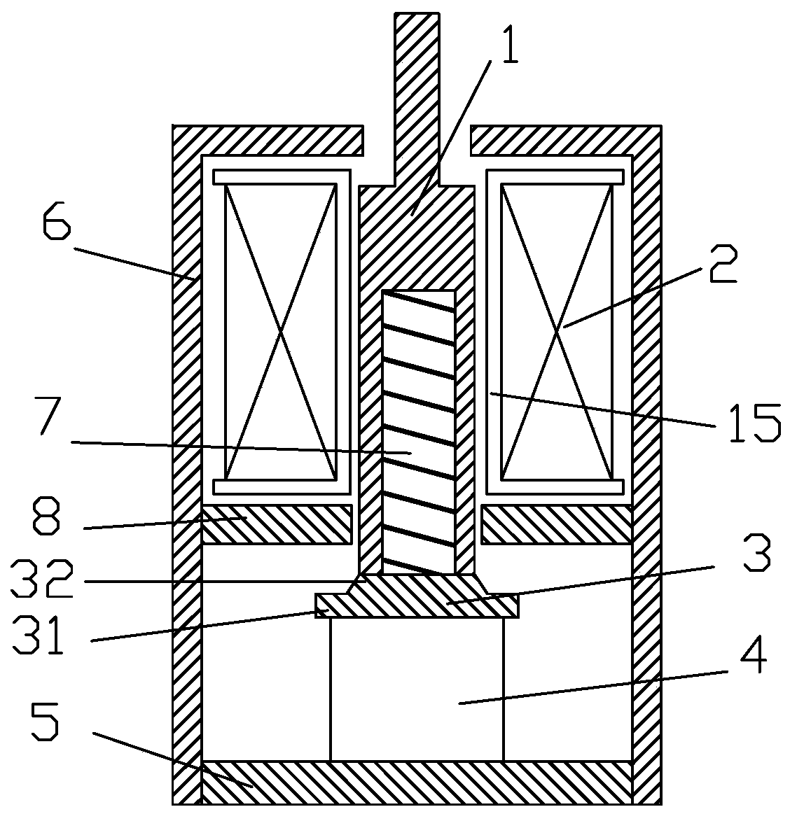
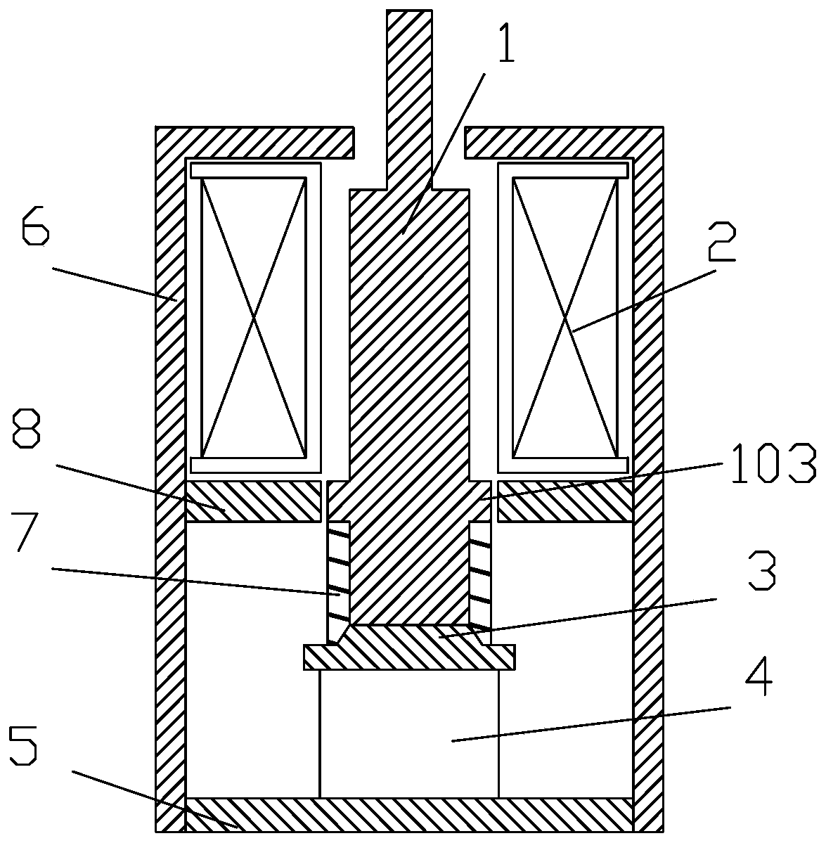
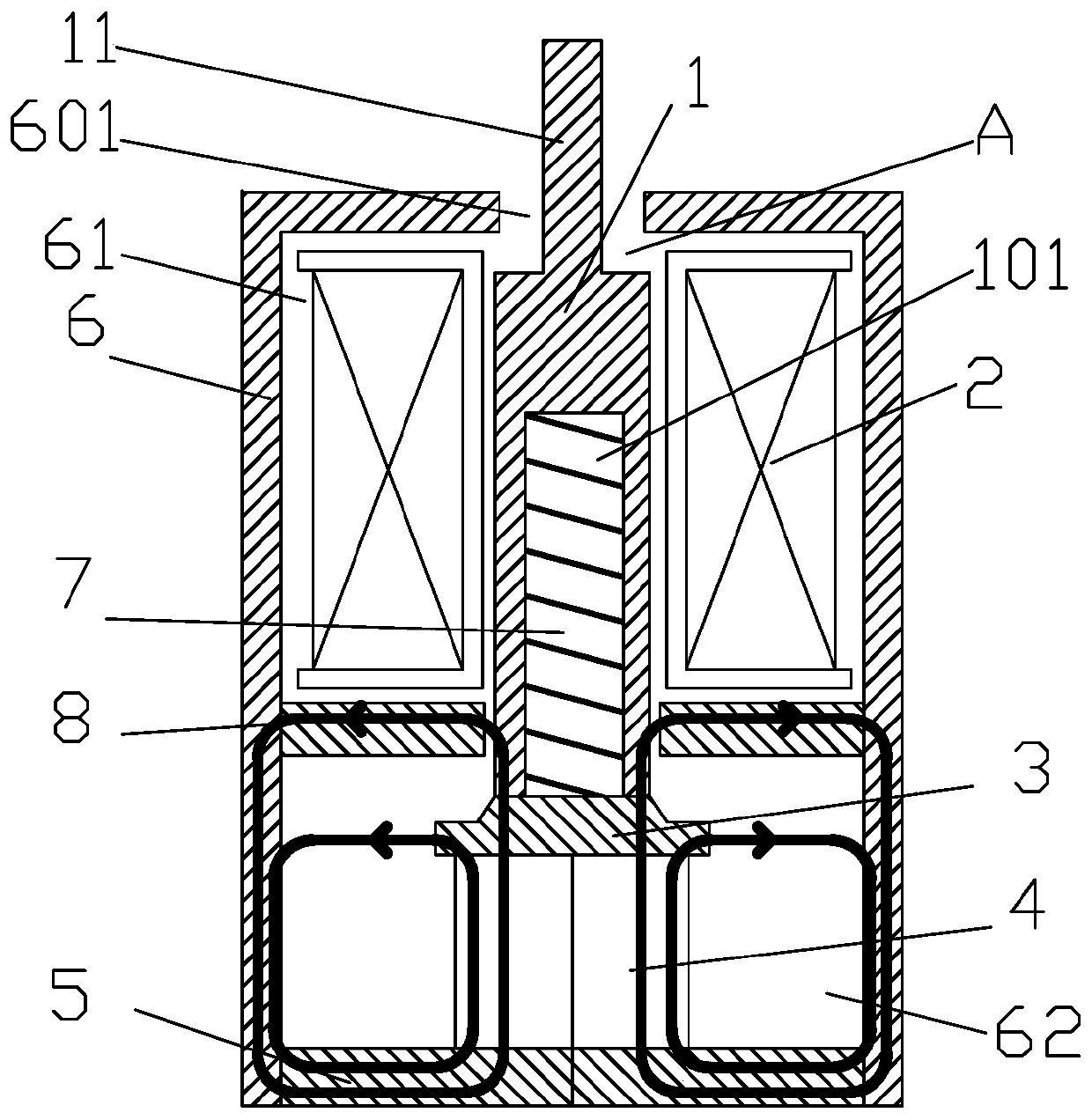
[0027] The following is attached Figures 1 to 6 The given examples further illustrate the specific implementation of the magnetic flux converter of the present invention. The flux converter of the present invention is not limited to the description of the following embodiments.

[0028] Such as Figure 1-6 As shown, the magnetic flux converter of the present invention includes a casing composed of a casing 6 and a rear cover 5, a bobbin 15 installed inside the casing, a coil 2 wound in the middle of the bobbin 15, a permanent magnet 4, an iron core 1 and a The iron core 1 is connected to the spring 7 that provides elastic force for the iron core 1, and the permanent magnet 4 is the magnetic attraction force of the iron core 1 to attract the iron core 1; 1 The push rod 11 at the other end extends to the opening 601 at the top of the casing. The casing includes a casing 6 and a rear cover 5, the opening 601 is arranged on the top of the casing 6, the rear cover 5 is fastened...


PUM


Abstract

A magnetic flux converter, comprising a housing, a coil bobbin installed inside the housing, a coil wound in the middle of the coil bobbin, a permanent magnet, an iron core and a spring connected to the iron core, the top of the housing is provided with an opening, and one end of the iron core It is attracted to the permanent magnet, and the ejector rod at the other end of the iron core extends to the opening at the top of the housing; it also includes a magnetically conductive coil, which is located between the coil and the permanent magnet. In the magnetic flux converter of the present invention, a magnetic conducting coil is added between the coil and the permanent magnet, so that the magnetic force lines of the permanent magnet and the coil are redistributed, and the magnetic force lines of the permanent magnet and the coil pass through the magnetic conducting coil to form a new magnetic circuit; the electromagnetic field will change the permanent The magnetic path of the magnetic field makes it possible to make the resultant force of the electromagnetic force and the elastic force greater than the attraction force of the permanent magnet to the iron core, and the iron core can move and push out no matter when the permanent magnet is installed upright or reversely (or when a positive and negative power supply is applied to the coil). The ejector rod performs the tripping action.

Description

technical field [0001] The invention relates to the field of low-voltage electrical appliances, in particular to a magnetic flux converter for positive and negative power supplies. Background technique [0002] The magnetic flux converter is the executive element of the intelligent circuit breaker and an important connecting device between the electronic controller of the intelligent circuit breaker and the mechanically operated switch. The stable realization of its tripping function is related to the reliability of the intelligent circuit breaker. The most direct indicator of the quality of the circuit breaker. The flux converter is a small energy-storage electromagnet, which uses permanent magnet materials and springs to store energy, and the coil is powered by a current transformer through a capacitor. When the circuit is normal, the coil is not powered, the iron core remains in the suction state under the suction force of the permanent magnet, and the spring is compress...

Claims


Application Information

Patent Timeline
Patent Type & Authority Patents(China)
IPC IPC(8): H01H71/32
Inventor 黄其黄小勇王克明肖磊
Owner ZHEJIANG CHINT ELECTRIC CO LTD
Learn More