Multi-function fault current controller and control method

A fault current, multifunctional technology for control/regulation systems, conversion of DC power input to DC power output, emergency protection circuit devices for limiting overcurrent/overvoltage, etc.

Active Publication Date: 2018-05-25
INST OF ELECTRICAL ENG CHINESE ACAD OF SCI +1
View PDF7 Cites 7 Cited by
  • Summary
  • Abstract
  • Description
  • Claims
  • Application Information

AI Technical Summary

Problems solved by technology

Then for DC FACTS research, the existing research focuses on DC equipment with i

Method used


Image

  • Multi-function fault current controller and control method
  • Multi-function fault current controller and control method
  • Multi-function fault current controller and control method

Examples


Embodiment 1

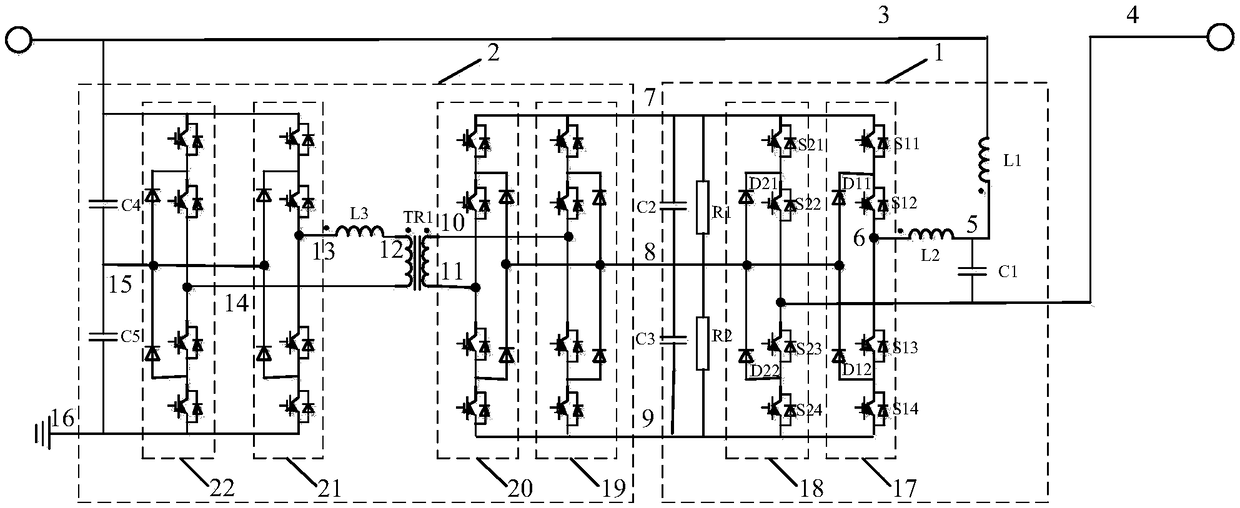
[0035] figure 1 Shown is Example 1 of the present invention. Such as figure 1As shown, the multifunctional fault current controller of the present invention includes a series converter circuit 1 and a parallel converter circuit 2 . The series converter circuit 1 includes a first inductor L1, a first capacitor C1, a second inductor L2, a first NPC bridge arm 17, a second NPC bridge arm 18, a second capacitor C2, a third capacitor C3, a first resistor R1 and The second resistor R2; the parallel converter circuit 2 includes a third NPC bridge arm 19, a fourth NPC bridge arm 20, a fifth NPC bridge arm 21, a sixth NPC bridge arm 22, a fourth capacitor C4, and a fifth capacitor C5 , the third inductor L3, and the first transformer TR1. The first lead-out terminal of the first inductor L1, the first lead-out terminal of the fifth NPC bridge arm 21, the first lead-out terminal of the sixth NPC bridge arm 22, and the first lead-out terminal of the fourth capacitor C4 are connected a...

Embodiment 2

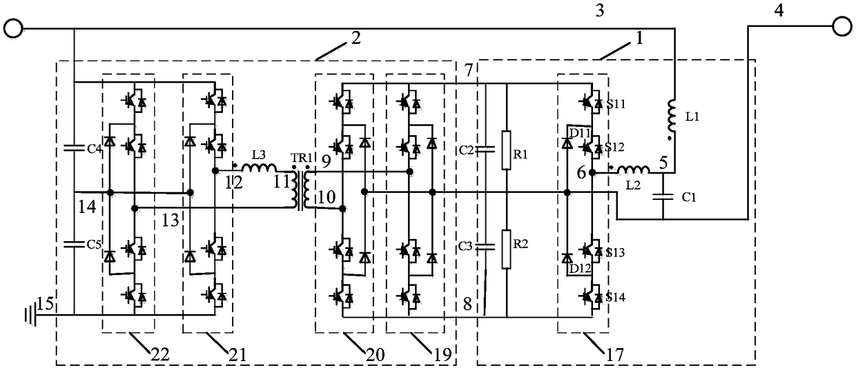
[0042] figure 2 Shown is Example 2 of the present invention. Such as figure 2 As shown, the multifunctional fault current controller of the present invention includes a series converter circuit 1 and a parallel converter circuit 2 . The series converter loop 1 includes a first inductor L1, a first capacitor C1, a second inductor L2, a first NPC bridge arm 17, a second capacitor C2, a third capacitor C3, a first resistor R1 and a second resistor R2; The parallel converter circuit 2 includes a second NPC bridge arm 19, a third NPC bridge arm 20, a fourth NPC bridge arm 21, a fifth NPC bridge arm 22, a fourth capacitor C4, a fifth capacitor C5, a third inductor L3, a A transformer TR1. The first lead-out terminal of the first inductor L1, the first lead-out terminal of the fourth NPC bridge arm 21, the first lead-out terminal of the fifth NPC bridge arm 22, and the first lead-out terminal of the fourth capacitor C4 are connected at the third connection point 3 ; The second ...

Embodiment 3

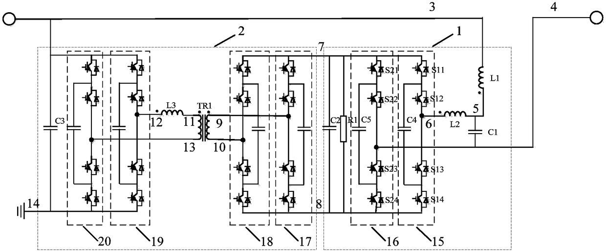
[0049] image 3 Shown is Example 3 of the present invention. Such as image 3 As shown, the multifunctional fault current controller of the present invention includes a series converter circuit 1 and a parallel converter circuit 2 . The series converter circuit 1 includes a first inductor L1, a first capacitor C1, a second inductor L2, a first capacitor clamping three-level bridge arm 15, a second capacitor clamping three-level bridge arm 16, a second capacitor C2, The first resistor R1; the parallel converter circuit 2 includes a third capacitor-clamped three-level bridge arm 17, a fourth capacitor-clamped three-level bridge arm 18, a fifth capacitor-clamped three-level bridge arm 19, and a third capacitor-clamped three-level bridge arm 19. The six capacitors clamp the three-level bridge arm 20 , the third capacitor C3 , the third inductor L3 and the first transformer TR1 . The first lead-out terminal of the first inductor L1, the first lead-out terminal of the fifth capac...


PUM


Abstract

The invention relates to a DC power distribution network multi-function fault current controller and a control method. The multi-function fault current controller is formed by a series convertor loop(1) and a parallel convertor loop (2). The series convertor loop (1) is formed by an NPC full-bridge circuit, an LCL filter, a DC capacitor and a DC bleeder resistor. The parallel convertor loop (2) is formed by an NPC three-level DAB circuit. Under a stable state, the fault current controller can compensate circuit voltage surge, sag and pulsation; and under a fault state, the fault current controller can provide current-limiting inductance and backward voltage, thereby comprehensively realizing multiple functions of voltage regulation of a DC power distribution network and current limiting and blocking of the fault current, and improving use efficiency of the fault current controller.

Description

technical field [0001] The invention relates to a multifunctional fault current controller and a control method for a direct current distribution network, belonging to the technical field of direct current distribution networks. Background technique [0002] Compared with the AC distribution network system, the DC distribution network can directly connect various power sources and loads to the system through DC / DC converters, without additional energy conversion links, which greatly improves the transmission efficiency of the distribution network. In addition, DC distribution networks deliver higher power than AC systems at comparable voltage levels, conductor cross-sections, current densities, and corridor widths. At the same time, the DC distribution network does not have synchronization problems such as frequency and phase of the AC system, and it has obvious technical advantages when the distributed power is connected to the grid. For the increasingly tense urban popula...

Claims


Application Information

Patent Timeline
IPC IPC(8): H02H9/02H02J1/10H02M3/335
CPCH02H9/02H02J1/102H02M3/33584
Inventor 尹靖元吴理心黄强袁晓冬李强李娟韦统振
Owner INST OF ELECTRICAL ENG CHINESE ACAD OF SCI
Why Eureka
Try Eureka