Energy-saving device and method for transformer in solar power station

A technology of energy-saving devices and power stations, applied in circuit devices, photovoltaic power generation, electrical components, etc., can solve problems affecting other users, shortening service life, voltage and current impact, etc., achieves good application prospects, reduces electricity costs, and saves The effect of energy consumption

Pending Publication Date: 2018-05-25
JIANGSU BLUE SKY PHOTOVOLTAIC TECH
View PDF6 Cites 0 Cited by
  • Summary
  • Abstract
  • Description
  • Claims
  • Application Information

AI Technical Summary

Problems solved by technology

[0006] The excitation inrush current is related to the phase angle of the system voltage when the transformer is switched on, the residual magnetic flux of the transformer iron core, and the impedance of the power supply system. , In some cases, the inrush current can cause electric fluctuations. If no corresponding measures are taken, it may cause overcurrent of the transformer or malfunction of relay protection, resulting in power failure and affecting the use of other users.
In addition, high-voltage transformers do no-load closing operations every day to generate voltage and current shocks, thermal shocks, and electromagnetic effects caused by inrush currents, which will cause mechanical forces and vibrations inside the transformer, thereby shortening its service life.
[0007] In order to meet the needs of photovoltaic power generation, the transformer can be withdrawn at night, so as to save energy consumption and reduce electricity costs. At the same time, it is a technical problem to be solved that the transformer should be put into operation in time before power generation without reducing reliability and equipment life.

Method used


Image

  • Energy-saving device and method for transformer in solar power station

Examples


Embodiment Construction

[0031] The present invention will be further described below in conjunction with the accompanying drawings.

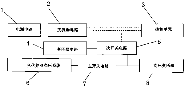
[0032] Such as figure 1 As shown, the energy-saving device for a transformer in a solar power station of the present invention includes a converter circuit 2, a control unit 3, a transformer circuit 4, a secondary switch circuit 5, a main switch circuit 7 and a high-voltage transformer 8,

[0033] The high-voltage transformer 8 is used to boost the low-voltage alternating current generated by the grid-connected inverter in the solar power station into a high-voltage alternating current, and transmit it to the photovoltaic grid-connected high-voltage system 6 through the main switch circuit 7, and the photovoltaic grid-connected high-voltage system 6 , for connecting the boosted high-voltage alternating current to the power grid, and the high-voltage transformer 8 can be one or multiple parallel connections;

[0034] The converter circuit 2 receives a given AC voltage ...


PUM


Abstract

The invention discloses an energy-saving device and method for a transformer in a solar power station. A current converter circuit, a control unit, a transformer circuit, a secondary switching circuit, a main switching circuit and a current converter circuit are added, and a given AC voltage instruction is received and an alternating current is generated, so as to supply a low-voltage exciting current to a no-load high-voltage transformer for excitation. The control unit is used for outputting the given AC voltage instruction to the current converter circuit, and controlling the on/off of thesecondary switching circuit and the main switching circuit. The transformer circuit is used for the boosting of the low-voltage exciting current of the current converter circuit, and achieves the excitation of the no-load high-voltage transformer. The photovoltaic power generation can be withdrawn from the high-voltage transformer, thereby saving the energy consumption and reducing the electricityfee. Meanwhile, the high-voltage transformer is timely put before the power generation, so the reliability is not reduced and the equipment service life is not shortened. The device is ingenious in idea, is convenient to implement, and is good in application prospect.

Description

technical field [0001] The invention relates to the technical field of photovoltaic power generation, in particular to an energy-saving device and method for a transformer in a solar power station. Background technique [0002] With the rapid development of new energy technology, solar power generation has been widely used and developed rapidly. The main method of solar grid-connected power generation system is to output the photovoltaic grid-connected inverter in the photovoltaic module through a step-up power transformer (such as a box-type substation). Electric energy is fed into the grid (the voltage level in China is usually 10kV or 35kV), and currently there is actually no consideration of the energy waste of these power transformers consuming energy at no load when power generation is stopped at night. [0003] The solar grid-connected power generation system can collect solar radiation energy. Generally, the photovoltaic effect is used to convert solar radiation ener...

Claims


Application Information

Patent Timeline
Patent Type & Authority Applications(China)
IPC IPC(8): H02J3/38
CPCH02J3/383Y02E10/56
Inventor 瞿冲史君海白正阁姜绪李成喜瞿建国
Owner JIANGSU BLUE SKY PHOTOVOLTAIC TECH
Why Eureka
Try Eureka