Constant current charging-discharging pulse charger

A pulse charging and charging-discharging technology, applied in the electronic field, can solve the problems of not being scientific enough, not realizing charging, etc.

Inactive Publication Date: 2018-05-25
CHONGQING NINGLAI SCI & TRADE
View PDF0 Cites 2 Cited by
  • Summary
  • Abstract
  • Description
  • Claims
  • Application Information

AI Technical Summary

Problems solved by technology

[0004] The reason why the most scientific charging has not been realized is that the current products either only use DC to charge the battery, but do not use a better method, such as constant current chargi

Method used


Image

  • Constant current charging-discharging pulse charger
  • Constant current charging-discharging pulse charger

Examples


Embodiment Construction

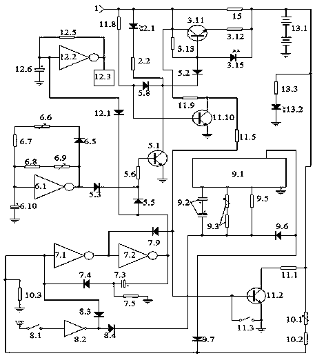
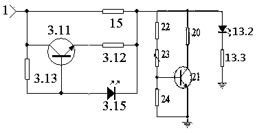
[0102] figure 1 An example of an implementation artifact is given, figure 2 Example of detection map in implementation.

[0103] 1. Selection of components: 1. The counter is an integrated circuit CD4060 composed of an oscillator and a binary serial counter.

[0104] 2. The inverters are welded with Schmidt circuit.

[0105] 3. All the transistors in the measure are NPN transistors of the same type.

[0106] 4. The tuning indicator is a light emitting tube.

[0107] 2. Make the circuit control board, welding components: connect figure 1 Make the circuit control board according to the schematic diagram, connect figure 1 Schematic of soldered components.

[0108] 3. Power-on inspection and debugging.

[0109] Check that the welding is correct, and can conduct power-on inspection and debugging

[0110] 1. Check the constant current source part.

[0111] Such as figure 2 Solder a dummy load in place of the battery being charged as shown. Connect a triode to form an ad...


PUM


Abstract

The invention discloses a constant current charging-discharging pulse charger, and belongs to the technical field of electronics. The constant current charging-discharging pulse charger is composed ofa process indicting unit, a voice prompt unit, an N-type charging unit, an N-type discharging unit, an interface unit, a pulse unit, a double-selection termination unit, a load unit, and a trickle resistor. The N-type charging unit, the N-type discharging unit and the pulse unit, and the interface unit form a pulse charging form that is capable of charging and discharging and having a charging time longer than the discharging time. A constant current triode of the N-type charging unit is connected in the form of constant current, therefore forming constant current charging. The constant current charging-discharging pulse charger has termination after the full charging of the battery and termination after the end of the timing countdown which can easily switch. After the end of charging ordischarging, the trickle resistor provides required trickle current to a to-be-charged battery, the inverter in each unit is formed of a gate circuit that has mutation input and output. The constantcurrent charging-discharging pulse charger has strong loading capability. After the implementation, the constant current charging-discharging pulse charger can flexibly adjust the charging and discharging time of the to-be-charged power supply and is suitable to to-be-charged batteries of different types.

Description

technical field [0001] It belongs to the field of electronic technology. Background technique [0002] Our company applied for a series of security products some time ago, and this product must have a backup battery, otherwise, when there is no mains power, the security function will become a fake, and when there is no mains power, it may be the peak of security accidents when. So a backup battery is required. And the performance of the backup battery is directly related to the overall performance. [0003] But the backup battery must be charged and maintained, and the scientific maintenance of the backup battery is directly related to the life and capacity of the backup battery. Some sources believe that batteries are often not worn out, but damaged due to improper charging. Batteries in security equipment are special-purpose batteries, which have special requirements for volume and capacity, and are more demanding than general products. [0004] The reason why the mos...

Claims


Application Information

Patent Timeline
IPC IPC(8): H02J7/00H02J7/34
CPCH02J7/0068H02J7/00711H02J7/345
Inventor 不公告发明人
Owner CHONGQING NINGLAI SCI & TRADE
Why Eureka
Try Eureka