Rotary speed control system and method of permanent magnet synchronous motor

A permanent magnet synchronous motor, permanent magnet synchronous technology, which is applied in the direction of single motor speed/torque control, motor generator control, electronic commutation motor control, etc., can solve the problems of difficult parameter adjustment, complicated controller design, etc. The effect of reducing adjustment difficulty, improving anti-disturbance performance and simple design

Active Publication Date: 2018-05-29
QINGDAO UNIV
View PDF4 Cites 16 Cited by
  • Summary
  • Abstract
  • Description
  • Claims
  • Application Information

AI Technical Summary

Problems solved by technology

[0003] In order to solve the problems of complex controller design and difficult parameter adjustment in the prior art, the present invention discloses a permanent magnet synchronous motor speed control system and method. The method is based on backstepping control and nonlinear observer to design permanent magnet synchronous motors. The speed-current single-loop controller of the drive system replaces the traditional speed loop and current loop cascaded control to achieve fast and stable speed tracking. It is a new method to use advanced algorithms to realize motor speed control

Method used


Image

  • Rotary speed control system and method of permanent magnet synchronous motor
  • Rotary speed control system and method of permanent magnet synchronous motor
  • Rotary speed control system and method of permanent magnet synchronous motor

Examples


Embodiment Construction

[0053] The present invention will be further described below in conjunction with the accompanying drawings and specific embodiments.

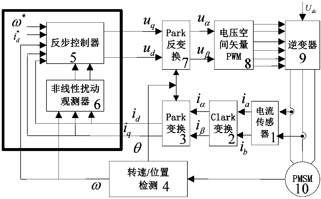
[0054] Such as figure 1 As shown, a permanent magnet synchronous motor speed control system includes: current sensor module, Clark coordinate transformation module, Park coordinate transformation module, speed / position detection module, backstepping controller, nonlinear disturbance observer, and Park coordinate inverse transformation module, voltage space vector PWM module and inverter;

[0055] The current sensor module is connected with the permanent magnet synchronous motor, the current sensor module, the Clark coordinate transformation module, and the Park coordinate transformation module are connected in sequence, the Park coordinate transformation module is connected with the nonlinear disturbance observer and the backstepping controller respectively, and the nonlinear disturbance observer is connected with The backstepping controller i...


PUM


Abstract

The invention discloses a rotary speed control system and method of a permanent magnet synchronous motor. A current sensor module is connected with the permanent magnet synchronous motor; the currentsensor module, a Clark coordinate conversion module and a Park coordinate conversion module are connected in sequence; the Park coordinate conversion module is connected with a nonlinear disturbance observator and a back-stepping controller separately; the nonlinear disturbance observator is connected with the back-stepping controller; the back-stepping controller, a Park coordinate inverse conversion module, a voltage space vector PWM module and an inverter are connected in sequence; the inverter is connected with the permanent magnet synchronous motor; and a rotary speed / position detection module is connected with the nonlinear disturbance observator, the back-stepping controller, the Park coordinate conversion module and the Park coordinate inverse conversion module separately. By adopting back-stepping control and the nonlinear disturbance observator method to replace the conventional PI controller, and by adopting a rotary speed-current single loop control mode to replace the conventional rotary speed loop and current loop cascading control structure, quick tracking control of rotary speed and current is realized.

Description

technical field [0001] The present invention relates to a permanent magnet synchronous motor (PMSM) speed control system and method, in particular to a PMSM speed control based on backstepping control and nonlinear disturbance observer with strong tracking and robustness and easy adjustment of control parameters System and control method. Background technique [0002] Permanent magnet synchronous motor (permanent magnet synchronous motor, PMSM) has the advantages of high efficiency, high specific power, high reliability, and easy maintenance. It has been widely used in CNC machine tools, robots, electric vehicle drive systems, and wind power generation. High-speed rail, aerospace and other fields also have good application prospects. With the rapid development of modern industry, the performance requirements of the permanent magnet synchronous motor control system continue to increase. However, the permanent magnet synchronous motor is a complex multi-variable, strongly co...

Claims


Application Information

Patent Timeline
Patent Type & Authority Applications(China)
IPC IPC(8): H02P6/08H02P21/13H02P21/18
CPCH02P6/08H02P21/13H02P21/18
Inventor 刘旭东于海生于金鹏
Owner QINGDAO UNIV
Why Eureka
Try Eureka