Combined microstructure guide rail and manufacturing method thereof

A manufacturing method and micro-texturing technology, which can be used in manufacturing tools, large-scale fixed members, metal processing machinery parts, etc. Easy appearance, low cost, and low processing heat

Pending Publication Date: 2018-06-01
NANTONG UNIVERSITY +1
View PDF9 Cites 6 Cited by
  • Summary
  • Abstract
  • Description
  • Claims
  • Application Information

AI Technical Summary

Problems solved by technology

[0006] The present invention mainly aims at the problem that the working surface of the guide rail is easy to wear and crawl, but the single texture with complex morphology is difficult to process, and the function of part of the morphology and texture is limited, and proposes a combined micro-texture guide rail and its production method

Method used


Image

  • Combined microstructure guide rail and manufacturing method thereof
  • Combined microstructure guide rail and manufacturing method thereof
  • Combined microstructure guide rail and manufacturing method thereof

Examples


Embodiment 1

[0026] Example 1. The embodiment of the present invention provides a CA6140 ordinary lathe combined micro-texture guide rail preparation method, the steps are:

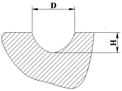
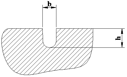
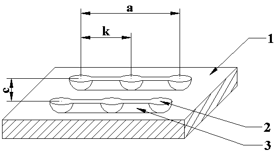
[0027] Step 1, CA6140 ordinary lathe, the guide rail type is a rectangular sliding guide rail, the specific geometric parameters of the shape of the micro-pits 2 are: pit diameter D=65um, pit depth H=5um, feature spacing k=225um, and feature area occupancy Rate S=5%. Specific geometric parameters of micro-groove 3 morphology: groove length a=100mm, groove width b=20um, groove depth h=5um, groove spacing c=225um.

[0028] Step 2, the guide rail surface 1 needs to undergo a pretreatment process before laser micromachining, and the pretreatment process adopts grinding to make the guide rail surface 1 precision meet the requirements of laser micromachining, surface roughness: the arithmetic mean deviation of the parameter profile Ra≤0.8 um, the maximum height of the profile Rz≤3.2um, geometric tolerance: both straightne...

Embodiment 2

[0033]Embodiment 2 is different from Embodiment 1 in that an oil distribution groove is provided on the surface of the guide rail along the length direction of the guide rail, and the shape of the oil distribution groove is a trigonometric function curve. The width of the oil distribution groove is t=1-2mm, and the depth is q=1mm-3mm. A CNC milling machine is used to process triangular function-shaped oil distribution grooves on the surface of the guide rail. The specific processing parameters are: spindle speed 200-600mm / s, feed rate 10-100mm, and cutting depth 1-3mm.

Embodiment 3

[0034] Example 3, such as Figure 5 As shown, the combined micro-texture topography of the present invention is applied to the static guide rail 7 of the triangular guide rail, corresponding to the moving guide rail 6 of the triangular guide rail.


PUM

PropertyMeasurementUnit
widthaaaaaaaaaa
depthaaaaaaaaaa

Abstract

The invention discloses a combined microstructure guide rail and a manufacturing method thereof, and relates to the technical field of surface treatment of machine tool guide rails. The combined microstructure guide rail is characterized in that a combined microstructure is distributed on the surface of the guide rail; the combined microstructure is in pit morphology and micro groove morphology; and the micro groove morphology is characterized in that micro grooves connected with single pits in the length direction of the guide rail are processed in micro pit morphology arrays. According to the combined microstructure guide rail, the crawling phenomenon of the guide rail is solved, lubricating performance is improved, abrasion resistance is improved, the service life of the guide rail canbe effectively prolonged, and comprehensive performance is improved.

Description

technical field [0001] The invention relates to a surface treatment technology of machine tool guide rails. Through laser micromachining and polishing technology, a combination of micro grooves and micro pits is formed on the surface of machine tool guide rails, and specifically relates to a surface micro texture guide rail technology in the machine tool industry. Applications. technical background [0002] With the advancement of science and technology, the demand for complex precision parts has increased significantly, and precision machine tools play an important role in the machinery manufacturing industry. The guide rail of the machine tool is a key component of the whole machine, and its performance directly affects the machining accuracy and the life of the machine tool. Common defects of machine tool guide rails include large guide rail contact area, uneven distribution of oil film, increased adhesive wear, guide rail surface is in a boundary lubrication state, incr...

Claims


Application Information

Patent Timeline
Patent Type & Authority Applications(China)
IPC IPC(8): B23Q1/01B23P15/00
CPCB23P15/00B23Q1/017
Inventor 朱维南王浩符永宏钟行涛韩洪松解玄康正阳
Owner NANTONG UNIVERSITY
Why Eureka
Try Eureka