Method for improving measuring accuracy of polarization performance of Y waveguide device

A waveguide device, accurate technology, applied in the field of polarization optical device measurement, can solve the problem of chip extinction ratio measurement error, not eliminating measurement error and other problems

Active Publication Date: 2018-06-01
HARBIN ENG UNIV
View PDF10 Cites 6 Cited by
  • Summary
  • Abstract
  • Description
  • Claims
  • Application Information

AI Technical Summary

Problems solved by technology

However, due to the structural and performance defects of the optical device itself, such as the polarizer/analyzer in the optical path to be tested, the polarization angle of the polarizer/analyzer usually deviates from the standard 45°, and this angle deviation directly

Method used


Image

  • Method for improving measuring accuracy of polarization performance of Y waveguide device
  • Method for improving measuring accuracy of polarization performance of Y waveguide device
  • Method for improving measuring accuracy of polarization performance of Y waveguide device

Examples


specific Embodiment approach 1

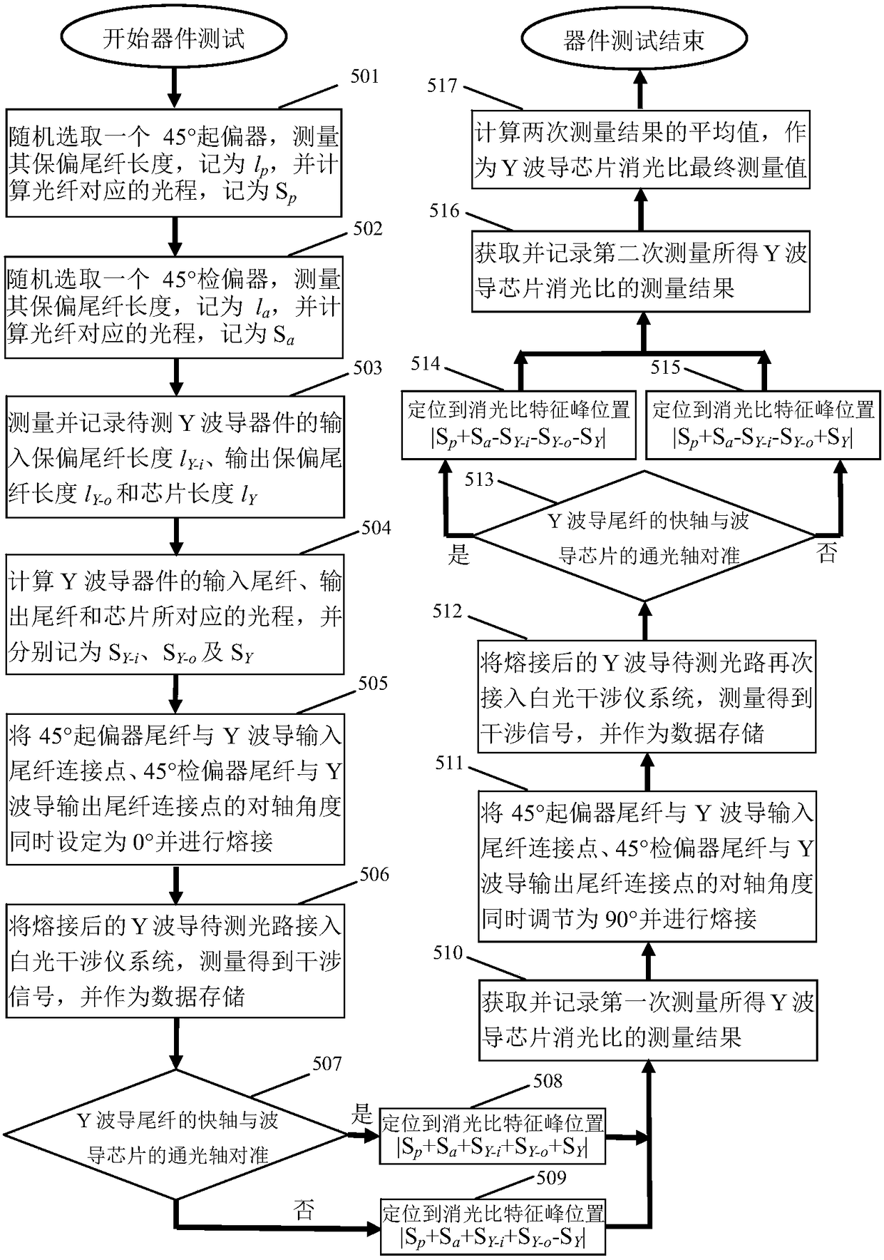
[0055] The specific embodiment one is a method for measuring the extinction ratio of a Y waveguide device chip, and the specific steps are:

[0056] (1) measure the length of the polarization-maintaining pigtail 202 of the randomly selected 45° polarizer 201, denoted as l p , and calculate the optical path corresponding to the fiber, denoted as S p = l p ×Δn b (Δn b is the linear birefringence of the polarization-maintaining pigtail);

[0057] (2) measure the length of the polarization-maintaining pigtail 208 of the randomly selected 45° analyzer 209, denoted as 1 a , and calculate the optical path corresponding to the fiber, denoted as S a = l a ×Δn b ;

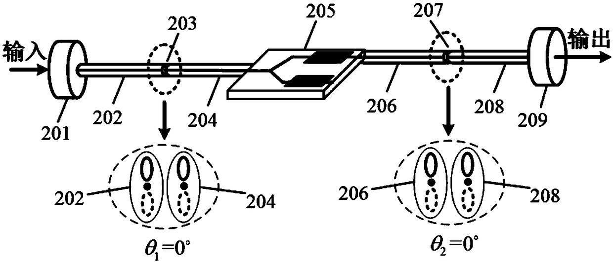
[0058] (3) measure and record the input pigtail 204 length l of the Y waveguide device to be tested Y-i , output pigtail 206 length l Y-o , and chip 205 length l Y ;

[0059] (4) Calculate the optical path corresponding to the input pigtail 204, the output pigtail 206, and the chip 205 of the Y waveguide device, ...

specific Embodiment approach 2

[0071] The second specific embodiment is a method for measuring the extinction ratio of a Y waveguide device chip, and the specific steps are:

[0072] (1) measure the length of the polarization-maintaining pigtail 202 of the randomly selected 45° polarizer 201, denoted as l p , and calculate the optical path corresponding to the fiber, denoted as S p = l p ×Δn b (Δn b is the linear birefringence of the polarization-maintaining pigtail);

[0073] (2) measure the length of the polarization-maintaining pigtail 208 of the randomly selected 45° analyzer 209, denoted as 1 a , and calculate the optical path corresponding to the fiber, denoted as S a = l a ×Δn b ;

[0074] (3) measure and record the input pigtail 204 length l of the Y waveguide device to be tested Y-i , output pigtail 206 length l Y-o , and chip 205 length l Y ;

[0075] (4) Calculate the optical path corresponding to the input pigtail 204, the output pigtail 206, and the chip 205 of the Y waveguide devic...

specific Embodiment approach 3

[0087] Specific embodiment three, on the basis of the above-mentioned first or second embodiment, the lengths of the polarization-maintaining pigtails 202 and 208 of the 45° polarizer and the 45° analyzer should meet the requirements of l as far as possible. p ≠l a , and require l p +l Y-i ≠ l a +l Y-o , in order to accurately judge and identify the meaning and position of each characteristic interference peak in the measurement interference signal.

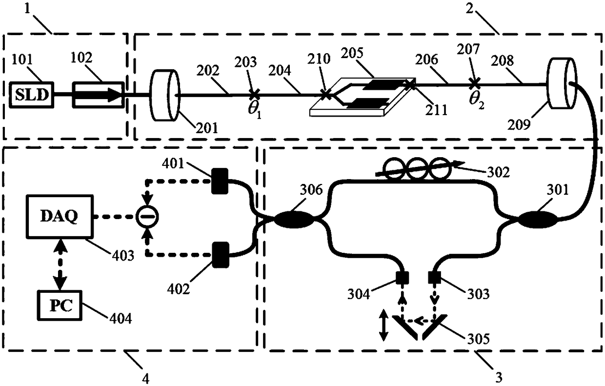
[0088] The polarization performance measurement device of Y waveguide device based on the principle of white light interference is attached figure 2 shown. After the wide-spectrum light source emitted by the light source module 1 passes through the Y-waveguide optical fiber optical path module 2 to be tested, the optical signal with the polarization characteristic of the Y-waveguide enters the scanning Mach-Zehnder interferometer module 3, and the interference signal finally reaches the signal detection and The data proces...


PUM


Abstract

The invention provides a method for improving the measuring accuracy of the polarization performance of a Y waveguide device. The method comprises the following steps: firstly, connecting an input polarization-maintaining tail fiber of a Y waveguide to be measured with a polarization-maintaining tail fiber connecting point of a polarizer, setting the countershaft angle of the output polarization-maintaining tail fiber of the Y waveguide and the polarization-maintaining tail fiber connecting point of a polarization analyzer to be 0 degree, obtaining a polarization parameter measurement result for the first time; simultaneously adjusting the countershaft angles of the two connecting points to be 90 degrees, so as to obtain a second measurement result; and finally, calculating the average value of the two measurement results as the final measurement value. According to the measuring method, a measuring optical path structure does not need to be changed, and the measuring method is simpleand effective, and easy to realize. The measurement error caused by the self structure and performance defect of a polarizer and a polarization analyzer in an optical path to be measured is eliminated, so that the measurement accuracy is further improved. The method can be widely applied to high-precision measurement of parameters such as extinction ratio of a Y waveguide device chip.

Description

technical field [0001] The present invention relates to a method for measuring polarized optical devices, specifically a method for measuring the polarization performance of a Y waveguide device, eliminating the measurement error introduced by the angle deviation of the polarizer / analyzer itself in the optical path to be measured, and further Ways to improve measurement accuracy. Background technique [0002] Multifunctional integrated optical chip (commonly known as Y waveguide), usually adopts titanium diffusion or high temperature proton exchange manufacturing process, and grows Y-shaped optical waveguide on lithium niobate substrate. The Y waveguide highly integrates the functions of single-mode optical waveguide, optical beam splitter, electro-optical phase modulator and optical polarizer. Due to its functional integration and miniaturization, it has gradually become an interferometric fiber optic gyroscope and fiber optic current The core components of high-precision ...

Claims


Application Information

Patent Timeline
IPC IPC(8): G01M11/02
CPCG01M11/00
Inventor 苑勇贵张浩亮杨军杨喆侯成城李寒阳苑立波
Owner HARBIN ENG UNIV
Why Eureka
Try Eureka