Boundary treatment method of coupling direct-current resistivity element-free method with finite element method

A finite element, DC resistance technology, applied in electrical digital data processing, special data processing applications, instruments, etc., can solve the problems of increasing the calculation cost of the elementless method, low calculation efficiency, and time-consuming

Active Publication Date: 2018-06-01
CENT SOUTH UNIV
View PDF2 Cites 4 Cited by
  • Summary
  • Abstract
  • Description
  • Claims
  • Application Information

AI Technical Summary

Problems solved by technology

However, in the traditional DC resistivity element-free method, because the calculation efficiency of the element-free method is not high, the third type of boundary condition is often used in the boundary processing to minimize the calculation domain and reduce the calculation cost, but in the multi-electrode case In this case, the element-free method is more time-consuming to deal with the third type of boundary
If the first type of boundary condition is used to eliminate the boundary calculation, a large enough calculation area is required. For any node distribution, the element-free method often requires a reasonable layout between nodes, and the expansion of the calculation area will seriously increase the calculation of the element-free method. cost

Method used


Image

  • Boundary treatment method of coupling direct-current resistivity element-free method with finite element method
  • Boundary treatment method of coupling direct-current resistivity element-free method with finite element method
  • Boundary treatment method of coupling direct-current resistivity element-free method with finite element method

Examples


Embodiment Construction

[0075] The present invention will be further described below in conjunction with the accompanying drawings and specific embodiments.

[0076] The DC resistivity observation and calculation method involved in the present invention comprises the following steps:

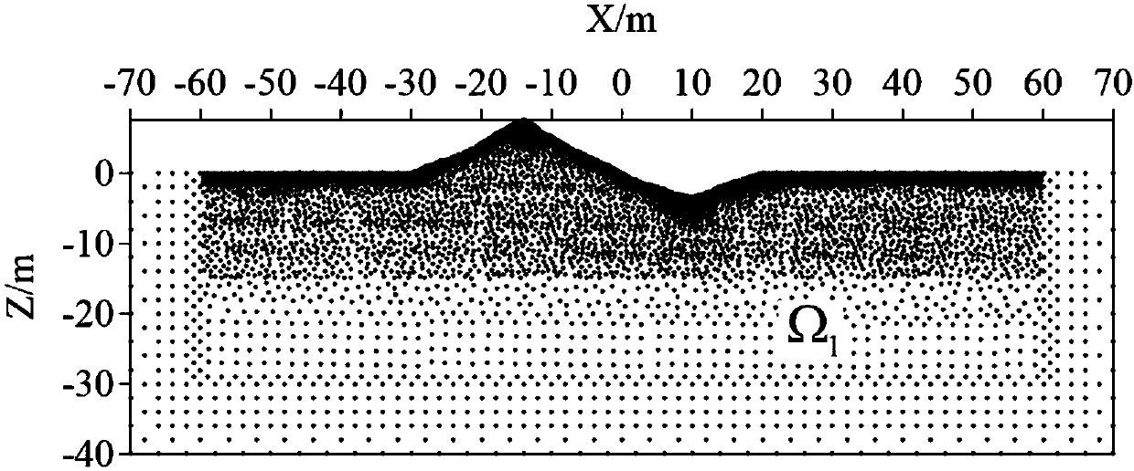
[0077] Step 1. The design of the parameter file of the forward modeling geoelectric model: according to the distribution of the dielectric resistivity in the two-dimensional geoelectric model, the geometric shape of the abnormal body and the terrain fluctuation, the confidence file of the discrete nodes of the model is set, and the electrode layout and the observation device are set. and element-free method-related parameters.

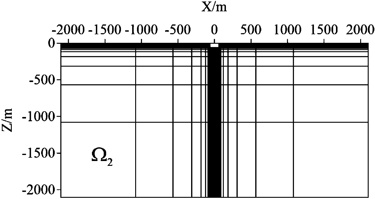
[0078] Step 2. Peripheral finite element method subdivision file: establish a finite element method mesh subdivision file in the peripheral area of ​​the model, and determine the area range, grid distribution, and node coordinates of the finite element method.

[0079] Step 3. Carry out elemen...


PUM


Abstract

The invention provides a boundary treatment method of coupling a direct-current resistivity element-free method with a finite element method. The boundary treatment method includes the steps of building a small-range element-free method area omega 1 to a two-dimension geoelectric model, calculating by the element-free method for the area, covering the element-free method area omega 1 with regularly distributed rectangular or parallelogram background grid to obtain an element-free method equation set of the area; subdividing the periphery of the element-free method area omega 1 by finite element method grid which is capable of rapid expansion, building a large-enough finite element method area omega 2 which meets requirements of first class of boundary conditions, calculating by the finiteelement method to obtain a finite element equation set of the area; combing the equation sets of the two areas and solving to obtain parameter of the apparent resistivity of an observation point. Themodels can be discrete on the basis of arbitrary node distribution by the method, the boundary treatment method has high adaptability to any complex geoelectric models, and calculation efficiency of forward modeling in the conventional direct-current resistivity element-free method is improved since boundary treatment is carried out by means of the finite element method.

Description

technical field [0001] The invention relates to a DC resistivity forward modeling method in the field of exploration geophysics, in particular to a high-precision, high-flexibility, high-adaptability and high-efficiency unit-free forward modeling method for complex geoelectric models. Background technique [0002] DC resistivity prospecting is an important method in geophysical prospecting, which is widely used in solid mineral resource prospecting, hydrogeological prospecting, environmental governance and monitoring, engineering geophysical prospecting and other fields. The measured apparent resistivity has a direct relationship with the resistivity of the underground medium. By artificially supplying electricity to the underground, observing the apparent resistivity on the surface or in the well can judge the distribution of underground resistivity anomalies. With the development of DC resistivity exploration technology, there is an increasing demand for high-precision, hi...

Claims


Application Information

Patent Timeline
Patent Type & Authority Applications(China)
IPC IPC(8): G06F17/50
CPCG06F30/23
Inventor 麻昌英柳建新刘海飞
Owner CENT SOUTH UNIV
Why Eureka
Try Eureka