Apparatus for ultrasonic-assisted machining

An auxiliary processing and ultrasonic technology, applied in the field of processing equipment, can solve problems such as unfavorable automatic production

Active Publication Date: 2018-06-05
METAL INDS RES & DEV CENT
View PDF11 Cites 3 Cited by
  • Summary
  • Abstract
  • Description
  • Claims
  • Application Information

AI Technical Summary

Problems solved by technology

Because the through hole on the resonant rod is a closed structure, the processing tool has only one degree of

Method used


Image

  • Apparatus for ultrasonic-assisted machining
  • Apparatus for ultrasonic-assisted machining
  • Apparatus for ultrasonic-assisted machining

Examples


Embodiment Construction

[0026] In order to solve the above-mentioned problems, the present invention provides an ultrasonic auxiliary processing device. The resonant rod has an unconstrained design relative to the processing tool / electrode, which can effectively achieve the function of ultrasonic vibration and tool / electrode exchange for automatic production, which is in line with industrial applications. need.

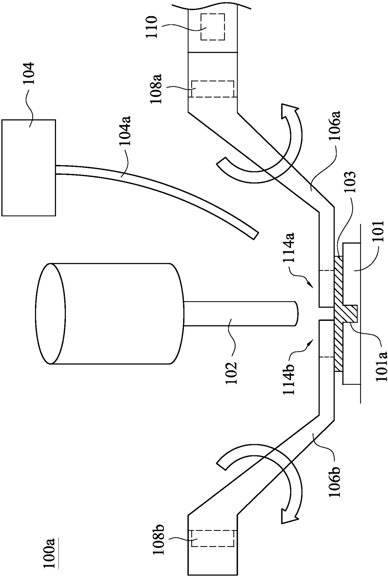
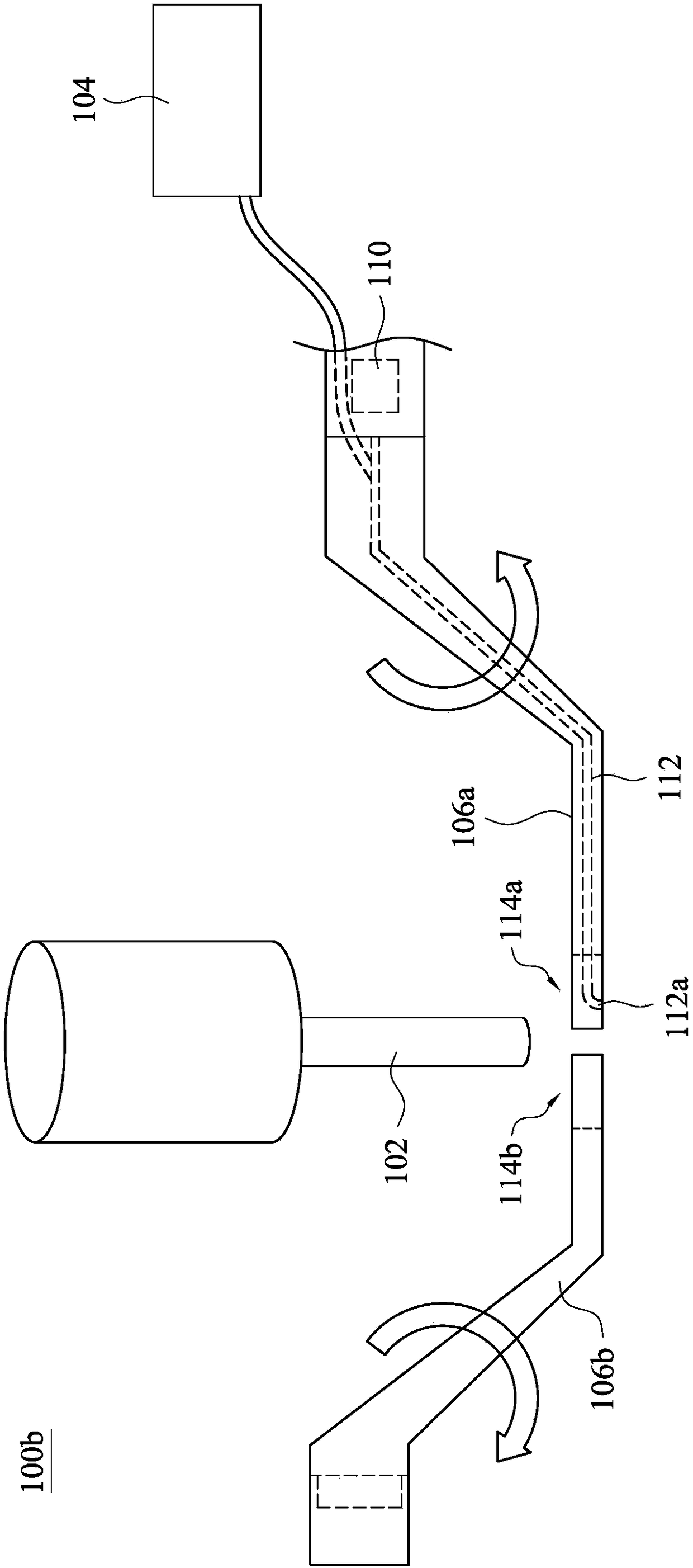
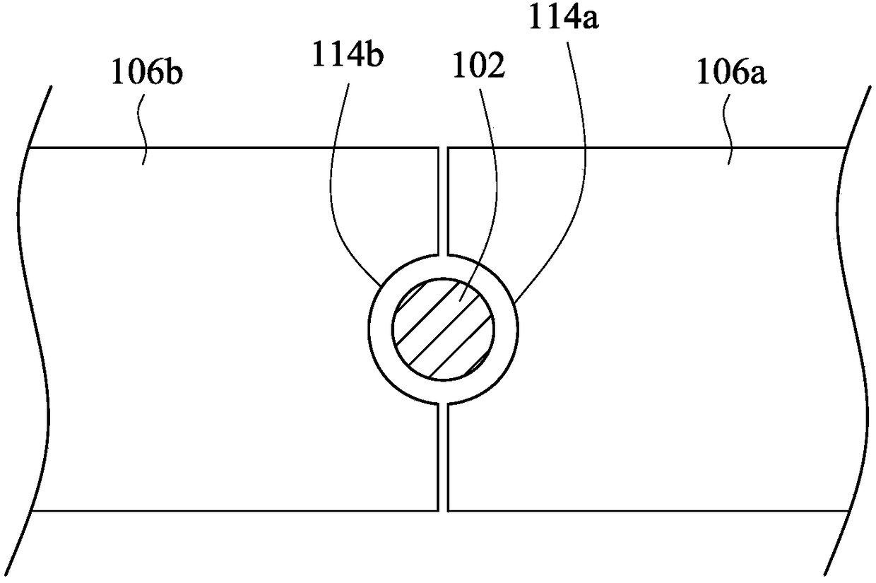
[0027] Please refer to figure 1 , which shows a schematic side view of the ultrasonic assisted processing device according to an embodiment of the present invention. The ultrasonic assisted processing device 100 a includes a processing tool 102 , a first resonant rod 106 a , a second resonant rod 106 b and a liquid supply unit 104 . In this embodiment, the processing tool 102 may be a discharge electrode for electric discharge machining, a drill bit, a milling cutter or other processing tools capable of forming holes 101 a on the surface of the object 101 to be processed. The liquid supply...


PUM


Abstract

The invention discloses an apparatus for ultrasonic-assisted machining. The apparatus comprises a machining tool, a first resonance rod, a second resonance rod and an ultrasonic oscillator, the firstresonance rod comprises a first non-closed gap, the second resonance rod comprises a second non-closed gap, and the ultrasonic oscillator transmits ultrasonic vibration through at least one of the first resonance rod and the second resonance rod. When machining is performed through the machining tool, the first non-closed gap and the second non-closed gap are arranged surrounding the machining tool. The requirement of more convenient replacement of machining tools including cutters and electrodes is met through the design of the resonance rods in the non-restricted structures with the cooperation of integration motion of a cylinder, a connecting trod mechanism and a tool machine so that the industrial application requirement of automation production is satisfied.

Description

technical field [0001] The invention relates to a processing device, in particular to an ultrasonic auxiliary processing device. Background technique [0002] The ultrasonic assisted machining device uses ultrasonic vibration to assist in the removal of processing chips during microhole machining. For example, when using a tool or electrode for microhole machining, ultrasonic vibration can effectively remove the material in the pores during processing. When the hole size is small and the aperture ratio is large, whether it is mechanical drilling, micro-discharge machining, etc., the machining chips are not easy to get rid of because the gap between the hole and the tool and electrode is very small, which will cause the tool to increase the force. Cause tool damage or processing failure. Another example is that in the micro-discharge process, machining chips are not easy to remove, resulting in poor machining efficiency or the inability to process holes with a large aperture...

Claims


Application Information

Patent Timeline
IPC IPC(8): B23B37/00B23H9/14
CPCB23B37/00B23H9/14
Inventor 庄殷浜田晴司孙义伟
Owner METAL INDS RES & DEV CENT
Why Eureka
Try Eureka