Anti-PID PERC battery structure and preparation method thereof

A battery and performance technology, applied in circuits, photovoltaic power generation, electrical components, etc., can solve the problems of poor thin layer compactness, thick thickness, and increased production costs, and achieve high compactness, good anti-PID effect, and excellent compactness. Effect

Pending Publication Date: 2018-06-05
TONGWEI SOLAR (ANHUI) CO LTD
View PDF3 Cites 1 Cited by
  • Summary
  • Abstract
  • Description
  • Claims
  • Application Information

AI Technical Summary

Problems solved by technology

[0002] Most of the back passivation methods of PERC batteries in the industry are plasma-enhanced chemical vapor deposition (PECVD). This structure of the battery only grows a thin layer of aluminum oxide on the back side and the thin layer is poor in density and thicker, and there is no thin layer of aluminum oxide on the front side. layer, such as a crystalline silicon solar cell and its manufacturing method with the application number "201310612665.3", which proves the combination of thermal oxidation, selective emission junction and back passivation, and a high conversion efficiency anti-PID solar cell with the application number "201710104735.2". N-type crystalline silicon double-sided battery and its preparation method, as well as a passivation film layer on the back of PERC battery with the application number "201710291291.8", and a PERC battery preparation method based on the ALD process. Although the battery structures of the above-mentioned several prior art can be Achieve the purpose of improving efficiency, but there are great risks in the face of increasingly strict anti-PID tests, and at the same time, the production cost is increased compared with the ALD coating method

Method used


Image

  • Anti-PID PERC battery structure and preparation method thereof
  • Anti-PID PERC battery structure and preparation method thereof
  • Anti-PID PERC battery structure and preparation method thereof

Examples


Embodiment Construction

[0022] The following will clearly and completely describe the technical solutions in the embodiments of the present invention with reference to the accompanying drawings in the embodiments of the present invention. Obviously, the described embodiments are only some, not all, embodiments of the present invention. Based on the embodiments of the present invention, all other embodiments obtained by persons of ordinary skill in the art without making creative efforts belong to the protection scope of the present invention.

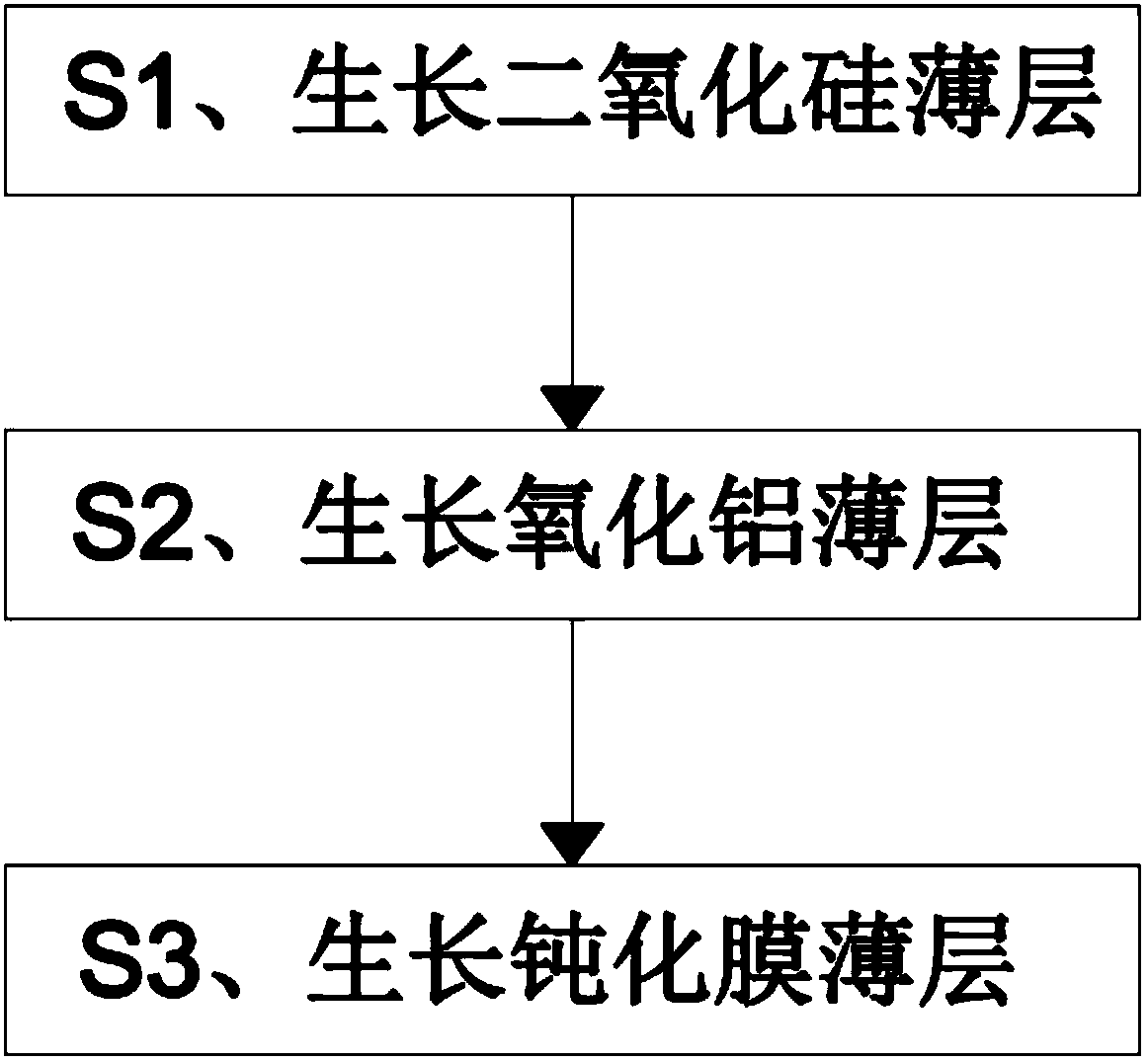
[0023] see Figure 1-2 , the present invention provides a technical solution:

[0024] A PERC battery structure with anti-PID performance, comprising a silicon substrate 1, the front side of the silicon substrate 1 is sequentially provided with a silicon dioxide layer 2 and a front silicon nitride layer 3, and the reverse side of the silicon substrate 1 is sequentially provided with a backside oxidation layer. Aluminum layer 4 and back silicon nitride layer 5...


PUM

PropertyMeasurementUnit
thicknessaaaaaaaaaa
thicknessaaaaaaaaaa
thicknessaaaaaaaaaa

Abstract

The invention discloses an anti-PID PERC battery structure. The anti-PID PERC battery structure comprises a silicon substrate, wherein a silicon dioxide layer and a front-surface silicon nitride layerare sequentially arranged on the front surface of the silicon substrate, and a back-surface aluminum oxide layer and a back-surface silicon nitride layer are sequentially arranged on the back surfaceof the silicon substrate; a front-surface aluminum oxide layer is arranged between the silicon dioxide layer and the front-surface silicon nitride layer, and the thickness of the front-surface aluminum oxide layer is 4nm+/-0.5nm; and the thickness of the silicon dioxide layer is 2nm+/-0.5nm; the thickness of the front-surface silicon nitride layer is 80+/-9nm; the thickness of the back-surface aluminum oxide layer is 4nm+/-0.5nm, and the thickness of the back-surface silicon nitride layer is 130nm+/-10nm. The invention further discloses a method for preparing the anti-PID PERC battery structure. The battery structure comprises a front-surface silicon nitride layer film, and the thickness of a front-surface aluminum oxide film layer and other film layers is reasonably designed, so that thebattery structure has relatively strong anti-PID performance, is very effective and is very worthy of being popularized.

Description

technical field [0001] The invention relates to the technical field of photovoltaic modules, in particular to a PERC cell structure with anti-PID performance and a preparation method thereof. Background technique [0002] Most of the back passivation methods of PERC batteries in the industry are plasma-enhanced chemical vapor deposition (PECVD). This structure of the battery only grows a thin layer of aluminum oxide on the back and the thin layer is poor in density and thicker, and there is no thin layer of aluminum oxide on the front. layer, such as a crystalline silicon solar cell and its manufacturing method with the application number "201310612665.3", which proves the combination of thermal oxidation, selective emission junction and back passivation, and a high conversion efficiency anti-PID solar cell with the application number "201710104735.2". N-type crystalline silicon double-sided battery and its preparation method, as well as a passivation film layer on the back ...

Claims


Application Information

Patent Timeline
Patent Type & Authority Applications(China)
IPC IPC(8): H01L31/0216H01L31/041
CPCH01L31/02167H01L31/041H01L31/02168H01L31/068Y02E10/547
Inventor 吴俊旻张鹏常青谢耀辉余波
Owner TONGWEI SOLAR (ANHUI) CO LTD
Why Eureka
Try Eureka