Improved trough-type ozone treatment system for processing solar cell silicon wafer

An ozone treatment and solar cell technology, applied in circuits, electrical components, sustainable manufacturing/processing, etc., can solve the problems of increasing labor and operating costs, unfavorable automation of the whole line, poor anti-PID effect, etc., to reduce labor costs and Production cost, increase the ease of use of the machine, and reduce the effect of design difficulty

Inactive Publication Date: 2019-05-31
NANJING FORESTRY UNIV
View PDF8 Cites 0 Cited by
  • Summary
  • Abstract
  • Description
  • Claims
  • Application Information

AI Technical Summary

Problems solved by technology

In order to improve the conversion efficiency of solar cells, it is necessary to effectively passivate the silicon wafers after surface texturing, and form a silicon dioxide film on the silicon surface by oxidation. At present, more processes are used to passivate silicon wafers with ozone gas. , that is, use gas spray equipment to spray reactive gas onto the surface of the silicon wafer to treat the surface, and form an oxide film on the surface of the silicon wafer to achieve the effect of anti-potential-induced decay (anti-PID), but an independent anti-PID is required After the machine is processed by wet cleaning, the surface is dried by drying or drying machine, and then oxidized in an independent machine. The process is relatively complicated, the oxidation is uneven, and the anti-PID effect is poor. It will lead to a decrease in the yield rate and increase the manpower and operating costs, which is not conducive to the automation of the entire line

Method used


Image

  • Improved trough-type ozone treatment system for processing solar cell silicon wafer
  • Improved trough-type ozone treatment system for processing solar cell silicon wafer
  • Improved trough-type ozone treatment system for processing solar cell silicon wafer

Examples


Embodiment Construction

[0030] The structural features, working principles and advantages of the present invention are described in detail as follows in conjunction with the accompanying drawings.

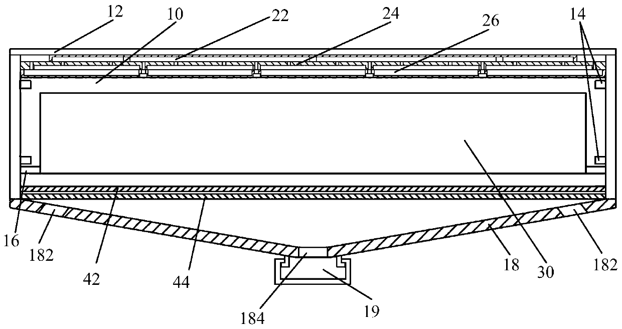
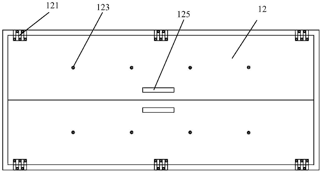
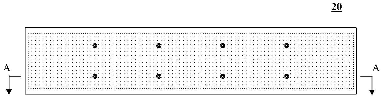
[0031] refer to figure 1 Shown is a schematic diagram of the composition of an improved trough ozone treatment system for solar cell silicon wafer processing according to an embodiment of the present invention. The trough ozone treatment system includes a tank body 10, a cover plate 12, and consists of three stages The ozone spray plate 20 formed by the air duct, the cover plate 12 and the spray plate 20 are fixed into an integral structure; the silicon chip loading flower basket 30 placed inside the tank body 10, and the fixing of the loading flower basket 30 placed in the tank body On the column 16; the ventilation system arranged under the loading flower basket 30, the ventilation system includes a first-level ventilation uniform plate 42, a secondary ventilation uniform flow plate 44, a funnel-shaped ...


PUM


Abstract

The invention provides an improved trough-type ozone treatment system for processing a solar cell silicon wafer, which comprises a trough body, a cover plate, an ozone spraying plate composed of a primary air trough, a secondary air trough, and a tertiary air trough, wherein the cover plate and the spraying plate are fixed to form an integrated structure; a silicon wafer carrying basket placed inside the trough body; and an air suction system disposed under the silicon wafer carrying basket and including a primary air suction airflow-sharing plate, a secondary air suction airflow-sharing plateand a funnel-shaped bottom plate, wherein the funnel-shaped bottom plate is provided with air suction ports on both sides, the central portion of the funnel-shaped bottom plate is provided with a silicon wafer debris outlet, a silicon wafer debris collecting box is disposed under the funnel-shaped bottom plate, and the inner walls on both sides of the trough body are provided with a plurality ofpressure sensors that sense the top intake pressure and the bottom exhaust pressures. The trough-type ozone treatment system of the invention can be widely integrated into a trough-type cleaning machine of a current solar cell production line to achieve a better anti-PID effect, and does not need an independent anti-PID machine, thereby greatly reducing the labor cost and production cost.

Description

technical field [0001] The invention relates to the technical field of photovoltaic power generation, in particular to an improved tank-type ozone treatment system for solar cell silicon wafer treatment. Background technique [0002] As the issue of global climate change is increasingly concerned by the world, clean energy such as photovoltaic power generation using solar energy has attracted more and more attention from various countries. Compared with traditional thermal power generation, an important reason affecting the rapid popularization of photovoltaic power generation is power generation. The cost is still relatively high, and an important way to reduce the cost of photovoltaic power generation is to improve the efficiency of photovoltaic power generation. [0003] At present, silicon substrate solar cells are the most used in the field of photovoltaics. The power generation efficiency of silicon substrate solar cells is directly related to the amount of sunlight th...

Claims


Application Information

Patent Timeline
Patent Type & Authority Applications(China)
IPC IPC(8): H01L31/18
CPCY02P70/50
Inventor 凡金星周宏平王影许林云杨言华
Owner NANJING FORESTRY UNIV
Why Eureka
Try Eureka