Pier plate column combination part structure

A joint and pier technology, applied in underwater structures, infrastructure engineering, building components, etc., can solve the problems of inconsistent design specification system, waste of resources, affecting the travel and life of surrounding people, and achieve design and calculation. Simple analysis, small underground space occupation, and implementable effect

Pending Publication Date: 2018-06-08
SHENZHEN MUNICIPAL DESIGN & RES INST
View PDF0 Cites 2 Cited by
  • Summary
  • Abstract
  • Description
  • Claims
  • Application Information

AI Technical Summary

Problems solved by technology

The reason is that the construction unit, design unit and construction unit of the viaduct and the underground space structure are two sets of personnel systems, and the design specification system is not unified. Conditions Affecting the Safety of Projects Completed Earlier
"Bridge first and then underground space structure" often adopts the means of bridge pile foundation underpinning or separated structure, and "first underground space structure and then bridge" often adopts the method of crossing the underground space structure such as prestressed caps or prestressed cap beams, repeatedly Excavation will cause a waste of resources and seriously affect the travel and life of the surrounding people

Method used


Image

  • Pier plate column combination part structure
  • Pier plate column combination part structure
  • Pier plate column combination part structure

Examples


Embodiment 1

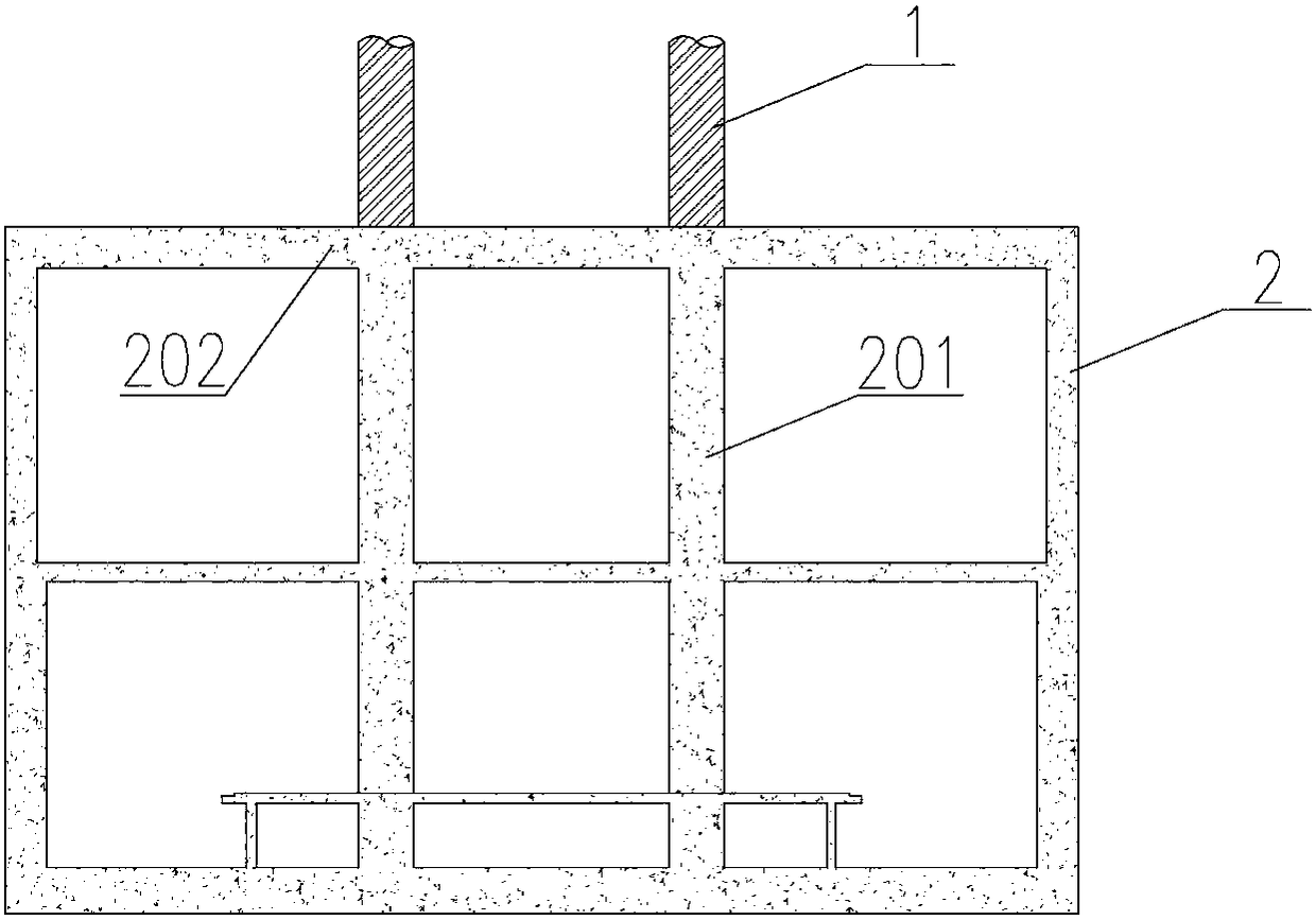
[0032] Such as figure 1 As shown, the present embodiment provides a piers-column joint structure, which includes bridge piers 1 and an underground space structure 2 fixedly connected to each other. The underground space structure 2 includes a column 201 and a roof 202. A plurality of columns 201 are embedded and supported underground. The top plate 202 is fixed on the top of a plurality of columns 201 , and the pier 1 is fixed on the top plate 202 ;

[0033] When the elevated bridge is built together with the underground space structure 2, such as figure 1 As shown, the arrangement of pier 1 along the direction of the bridge needs to be arranged in combination with the longitudinal spacing of the columns 201 of the underground space structure 2, and the pier 1 should be placed above the roof 202. To be aligned, the pier 1 passes through the roof 202 of the underground space structure 2 and is directly combined with the column 201 . If the bridge pier 1 is a reinforced concre...

Embodiment 2

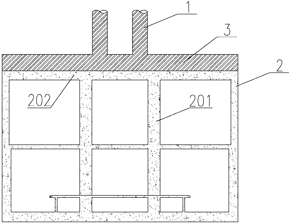
[0035] Such as figure 2 , 4 As shown, this embodiment provides a pier-column joint structure, which is basically the same in composition as in Embodiment 1, the only difference being:

[0036] When the pier 1 in the direction of the cross bridge cannot be vertically aligned with the column 201 of the underground space structure 2, a bench beam 3 can be installed on the top of the column 201, and the bench beam 3 can transfer the load of the pier 1 to the column 201 and the roof 202. The upright column 201 is combined together through the bench beam 3, and the bench beam 3 and the top plate 202 are also combined together, and the structure of the joint between the pier 1 and the bench beam 3 is as follows: Figure 4 shown. The bench beam 3 requires greater rigidity and strength, and it is recommended to adopt a reinforced concrete structure or a steel-reinforced concrete structure to facilitate the connection of the pier 1 with the roof 202 and the column 201 .

Embodiment 3

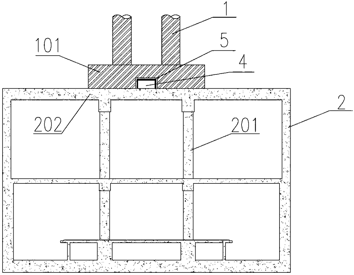
[0038] Such as image 3 As shown, this embodiment provides a pier-column junction structure, which is basically the same in composition as in Embodiment 1, the difference being:

[0039] When the pier 1 and the vertical column 201 in the direction of the transverse bridge cannot be aligned vertically, a raft foundation 101 can be placed under the pier 1, and the rigid layer can be placed on the roof 202. The raft foundation 101 can adopt a reinforced concrete solid structure or a cavity structure or a mesh structure. Grid structure, the steel-reinforced concrete grid structure or steel-reinforced concrete cavity structure is preferred here to reduce the weight of the superstructure and improve the safety of the underground space structure 2.

[0040] In order to improve the anti-seismic performance of the bridge structure, an anti-seismic shear pin 4 is set in the middle of the raft foundation 101, and rubber pads 5 are filled between the anti-seismic shear pin 4 and the raft ...


PUM


Abstract

The invention discloses a pier plate column combination part structure which comprises bridge piers which are mutually fixedly connected with each other and an underground space structure; the underground space structure comprises upright columns and a top plate; a plurality of upright columns are embedded into the ground and support underground; the top plate is fixed at the top ends of a plurality of upright columns; the bridge piers are fixed on the top plate; and a plurality of upright columns are arranged corresponding to a bridge direction of the bridge piers. The pier plate column combination part structure provided by the invention can have both the respective independent functions of an elevated bridge and the underground space structure; the bridge piers are combined with or separated from the top plate of the underground space structure, the arrangement of the bridge piers does not influence the function of the underground space structure, the underground space structure istaken as a bearing foundation of a bridge at the same time, separate independent design, construction and building of the elevated bridge and the underground space structure are facilitated, and the implementation of the bridge and the underground space structure is realized; and the bridge piers utilize the underground space structure as the bearing foundation, occupy less underground space, areconvenient in laying of underground pipelines and save underground precious space resources.

Description

technical field [0001] The invention relates to the technical fields of structural engineering and bridge engineering, in particular to a pier-slab-column junction structure. Background technique [0002] With the rapid development of cities, modern urban transportation such as underground rail transit, ground road systems and elevated bridges has been vigorously constructed. Limited by the width of planned roads, newly built viaducts, underground rail transit, underground shopping malls and other underground space structures often need to use the same underground resource space and share a corridor to achieve intensive land use, reduce demolition and impact on underground pipelines, and shorten the total construction period , saving investment. [0003] However, due to differences in construction processes, management systems, and construction subjects, when elevated bridges and underground space structures are built together, the phased construction method of "bridge firs...

Claims


Application Information

Patent Timeline
Patent Type & Authority Applications(China)
IPC IPC(8): E02D29/045E01D19/02E04B1/00E01D101/26E01D101/30
CPCE01D19/02E01D2101/26E01D2101/268E02D29/045E02D2300/002E02D2300/0029E04B1/0007
Inventor 何晓晖代亮郭明王梦雨
Owner SHENZHEN MUNICIPAL DESIGN & RES INST
Why Eureka
Try Eureka