
Drive units and units with coolers

A drive unit and unit technology, applied in electric components, machines/engines, liquid fuel engines, etc., can solve problems such as equipment technical costs of water circulation circuits, and achieve the effect of preventing dust

Active Publication Date: 2022-04-19
ROBERT BOSCH GMBH
View PDF10 Cites 0 Cited by
  • Summary
  • Abstract
  • Description
  • Claims
  • Application Information

AI Technical Summary

Problems solved by technology

[0005] A disadvantage of such a drive unit with an electric motor is the equipment-technical outlay for the water circuit, the frequency converter of which is cooled by means of a water-cooled cooling body

Method used


Image

  • Drive units and units with coolers
  • Drive units and units with coolers
  • Drive units and units with coolers

Examples


Embodiment Construction

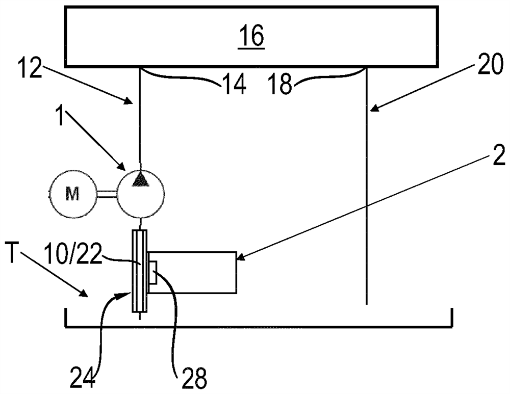
[0040] figure 1 A block diagram according to a first exemplary embodiment of the assembly according to the invention is shown. The assembly has a drive unit with an electric motor M and a hydrostatic pump 1 . The electric motor M of the drive unit is operated via a frequency converter 2 . Furthermore, the assembly has a tank T for a pressure medium, for example hydraulic oil.

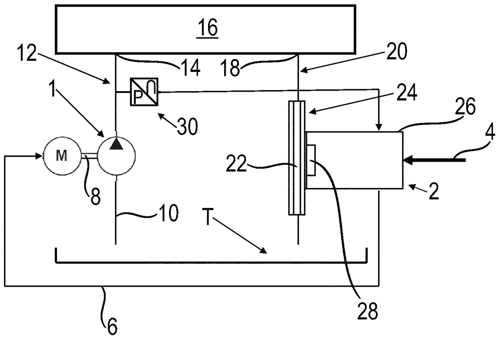
[0041] The frequency converter 2 is connected between the power supply 4 and the electrical line 6 , whereby the electric motor M is supplied with power via the electrical line 6 at a set frequency and thus at a set speed. The pump 1 is thus driven by the electric motor M via the shaft 8 at a variable speed. In this case, the pump 1 draws pressure medium from the tank T via a suction line 10 and delivers the pressure medium via a supply line 12 to a load connection 14 on the high-pressure side of the unit. A load, which can be a cylinder, for example, is connected to this load connection 14 via a va...


PUM


Abstract

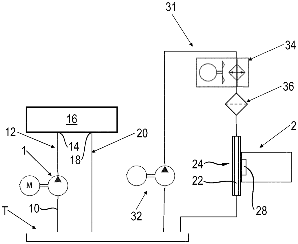
A frequency converter is disclosed having a cooler for an electric motor driving a hydrostatic pump. Cooling takes place via the working pressure medium delivered by the pump. In this case, the channels of the cooler can form a section of a hydraulic circuit which is fed by a pump, or which takes working pressure medium from a tank and feeds it to an additional cooling circuit line.

Description

technical field [0001] The invention relates to a drive unit with a hydrostatic pump, an electric motor and a cooled frequency converter. The invention also relates to an assembly with such a drive unit. Background technique [0002] It is known from the prior art to drive a hydrostatic pump via an electric motor, which supplies a hydraulic load, such as a motor or a hydraulic cylinder, via a hydraulic circuit. There is a frequency converter between the power supply and the motor, which generates waste heat. Most of the waste heat is generated at the power electronics or at the bipolar transistor(s) with an insulated gate (IGBT) and at the rectifier. For optimal conduction of the waste heat to the heat sink, the frequency converter or the IGBT and / or the rectifier are usually screwed directly onto the heat sink. The heat sink is made of a material with high thermal conductivity, for example aluminum. For optimal heat transfer, thermal paste is provided between the freque...

Claims


Application Information

Patent Timeline
Patent Type & Authority Patents(China)
IPC IPC(8): H02K9/20H02K11/33H02K9/19F04B17/03F04B53/08H02K5/20
CPCF04B17/03F04B53/08H02K11/33H02K7/14H02K9/227H02K5/203H02K9/225H02K9/19H05K7/20927
Inventor A.京德R.许特尔
Owner ROBERT BOSCH GMBH
Learn More