Eureka AIR delivers breakthrough ideas for toughest innovation challenges, trusted by R&D personnel around the world.

Centrifugal blood component separation cup and method

A technology for blood components and separation cups, applied in the field of medical devices, can solve the problems of time waste, adverse effects of blood donors' enthusiasm for donating plasma, and pollution of plasma components, so as to reduce plasma collection time, reduce the number of plasma collection cycles, and increase plasma collection. amount of effect

Pending Publication Date: 2018-06-12
董亚东 +1
View PDF0 Cites 6 Cited by
  • Summary
  • Abstract
  • Description
  • Claims
  • Application Information

AI Technical Summary

Problems solved by technology

[0005] 1. For those with low plasma content in blood donors, due to the limited capacity of the separation cup, the amount of plasma collected in a single time is often less than 300g, and multiple cycles are required to collect the target collection amount. The time required for blood transfusion will increase;
[0006] 2. For those with high plasma content in the blood of blood donors, due to the large capacity of the separation cup, the centrifuge cup needs to be filled to start collecting plasma, resulting in a waste of time;
[0007] 3. At the end of plasma collection, the blood entering the centrifuge cup is not completely separated, and the separation effect of plasma and red blood cells is poor, resulting in low separation quality;
[0008] 4. For those with low plasma content in blood donors, when the amount of plasma collected in a single time reaches the limit, red blood cells are easily mixed into the plasma collection bag, causing contamination of plasma components
[0009] The above deficiencies lead to too long time for blood donors to donate plasma, which will easily cause discomfort and take up blood donors' time, which will adversely affect the enthusiasm of blood donors to donate plasma, thus affecting the overall plasma collection volume

Method used


Image

  • Centrifugal blood component separation cup and method
  • Centrifugal blood component separation cup and method

Examples


Embodiment Construction

[0028] The present invention will be clearly and completely described below in conjunction with the accompanying drawings, so that those skilled in the art can fully implement the present invention without creative work.

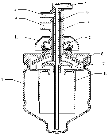
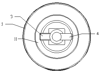
[0029] The specific embodiment of the present invention is: as figure 1 , 2 As shown, a centrifugal blood component separation cup includes a cup body 1, a stator 11, and a separation core 10. The inside of the cup body 1 is a hollow structure, and the stator 11 is arranged above the cup body 1. The stator 11 is Hollow structure, a red blood cell outlet 2, a plasma outlet 3 and a blood inlet 4 are arranged on the stator 11, a blood drainage catheter 9 is installed inside the stator 11, and a red blood cell drainage catheter 5 and a plasma drainage catheter 6 are arranged outside the blood drainage catheter 9 A cavity is formed between the blood drainage conduit 9 and the plasma drainage conduit 6, which communicates with the plasma outlet 3, and a cavity is...


PUM


Abstract

The invention provides a centrifugal blood component separation cup and method. The separation cup comprises a cup body, a stator and a separation core and is characterized in that the interior of thecup body is of a hollow structure, the stator of a hollow structure is arranged above the cup body, the stator is provided with a red-blood-cell outlet, a plasma outlet and a blood inlet, a blood drainage catheter is mounted inside the stator, a red-blood-cell drainage catheter and a plasma drainage catheter are arranged outside the blood drainage catheter, the separation core of a T-shaped structure is arranged on the upper portion of the interior of the cup body, a cavity is formed between the separation core and the cup body, the upper portion of the separation core is provided with two cavities, the outer cavity is a red-blood-cell buffer cavity, and the inner cavity is a plasma buffer cavity. The centrifugal blood component separation cup has the advantages that red blood cells are transferred out of the cup body through the red-blood-cell drainage catheter to allow more blood to enter the cup body and be separated so as to fast reach the target value of to-be-collected plasma, and the plasma donating time of a blood donor can be shortened while blood component separation quality is improved.

Description

technical field [0001] The invention relates to a medical device, in particular to a centrifugal blood component separation cup and a separation method. Background technique [0002] In medical applications, the treatment technology of plasma exchange and blood products or medicines based on plasma are commonly used. Plasma is an important component of human blood. Plasma collection technologies include membrane filtration technology and centrifugal separation technology. In order to obtain plasma components, centrifugal separation technology needs to use plasma collection equipment, and then use disposable blood collection tubes, collection bags and separation cups to extract human blood and inject it into the separation cup. Based on the principle of different centrifugal forces, each component in the blood forms different layers in the separation cup, the innermost layer is the plasma layer, and the outermost layer is the red blood cell layer. The current method of colle...

Claims


Application Information

Patent Timeline
IPC IPC(8): A61M1/02
CPCA61M1/0272
Inventor 董亚东
Owner 董亚东
Why Eureka
Eureka Blog
Learn More