
Laser forming method of gradient composite structure

A laser forming and composite structure technology, applied in the direction of process efficiency improvement, energy efficiency improvement, additive manufacturing, etc., can solve the problems of interface cracking between transition layers, large interlayer stress of transition layer, low strength of transition layer, etc. Small stress, continuous transition of components, and the effect of improving bonding strength

Active Publication Date: 2018-06-12
AEROSPACE INST OF ADVANCED MATERIALS & PROCESSING TECH
View PDF10 Cites 7 Cited by
  • Summary
  • Abstract
  • Description
  • Claims
  • Application Information

AI Technical Summary

Problems solved by technology

[0004] The above-mentioned mainstream laser forming methods for gradient composite structures all adopt the control of powder feeding amount of different components to achieve the purpose of manufacturing gradient composite structures. This method is very effective for component control, but there are certain problems, mainly in The scanning trajectory is carried out line by line and layer by layer according to the outline. This scanning method cannot effectively solve the problem of large interlayer stress in the transition layer, which leads to problems such as interface cracking between transition layers or too low strength of the transition layer in the actual manufacturing process.

Method used


Image

  • Laser forming method of gradient composite structure
  • Laser forming method of gradient composite structure
  • Laser forming method of gradient composite structure

Examples


Embodiment 1

[0038] TA15 alloy and Ti2AlNb alloy gradient composite structural parts (size 50*50*60) are prepared by laser stereoforming technology. The equipment used is laser stereoforming equipment, which includes 4KW carbon dioxide fast axial flow laser, powder feeding system, purification system, numerical control System, when using laser stereoforming technology to manufacture parts, the titanium alloy powder used is produced by plasma rotating electrode atomization method, with a particle size of about 90-400μm.

[0039] The steps are shown in 5:

[0040] 1. Initialize the laser forming equipment

[0041] Turn on the laser for preheating, check and prepare for each system of the laser forming equipment as required, and put TA15 alloy and Ti2AlNb alloy powder into powder feeding tanks 1 and 2 respectively.

[0042] 2. Scanning trajectory design of TA15 alloy and Ti2AlNb alloy transition layer

[0043] After the cladding of the entire TA15 alloy is completed, the initial layer of th...

Embodiment 2

[0053] In this example, laser three-dimensional forming technology is used to prepare and manufacture TA15, Ti2AlNb titanium alloy gradient composite structural sample with a size of Φ130mm×200mm. The equipment used is laser three-dimensional forming equipment, which includes 4KW carbon dioxide fast axial flow laser, powder feeding system, purification System, numerical control system, when using laser three-dimensional forming technology to manufacture parts, the titanium alloy powder used is produced by plasma rotating electrode atomization method, with a particle size of about 90-400μm.

[0054] Proceed as follows:

[0055] 1. Initialize the laser forming equipment

[0056] Turn on the laser for preheating, check and prepare for each system of the laser forming equipment as required, and put TA15 alloy and Ti2AlNb alloy powder into powder feeding tanks 1 and 2 respectively.

[0057] 2. Scanning trajectory design of TA15 alloy and Ti2AlNb alloy transition layer

[0058] Af...


PUM

PropertyMeasurementUnit
Thicknessaaaaaaaaaa

Abstract

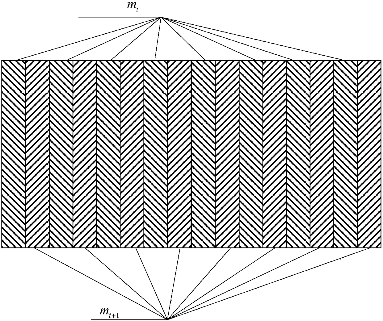
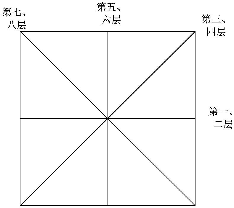
The invention provides a laser forming method of a gradient composite structure. The gradient composite structure is obtained through the steps of preparing of laser forming equipment, design of a laser forming technology, laser forming and the like. According to the laser forming method, by designing scanning trajectories of transition layers, the scanning trajectories between the two adjacent layers are nested mutually, so that interlayer stress between the transition layers is reduced and counteracted; and meanwhile, combination of the transition layers is converted from plane combination into stereo combination through a mutually-nested mode, so that the combination strength of the transition layers is improved, and finally the gradient composite structure which achieves component continuous transition and is small in interfacial stress and higher in overall strength is obtained.

Description

technical field [0001] The invention relates to a laser forming method of a gradient composite structure, which belongs to the technical field of metal special forming processing. Background technique [0002] The metal gradient composite structure has dual characteristics and has been widely used in actual production. Laser forming technology uses high-power laser to melt synchronously transported alloy powder, and accumulates layer by layer on the substrate to prepare near-net-shaped parts. It is a low-cost and rapid preparation technology for high-performance, fully dense metal parts. The characteristics of point-by-point addition of material forming, this technology has great flexibility in material composition, solidified structure, and external dimensions, and is suitable for the forming and preparation of gradient composite structures. However, during the forming process of gradient materials, due to the large difference in material structure and the mismatch of ther...

Claims


Application Information

Patent Timeline
IPC IPC(8): B22F3/105B33Y10/00
CPCB33Y10/00B22F2999/00B22F10/00B22F10/25B22F10/366B22F2207/01Y02P10/25
Inventor 吴海峰高源源邱美玲
Owner AEROSPACE INST OF ADVANCED MATERIALS & PROCESSING TECH
Learn More