Safety interlocking method of continuous wind tunnel cooling system

A technology of safety interlocking and system safety, which is applied in the field of safety interlocking of continuous wind tunnel cooling systems, and can solve the problems of oxygen deficiency of personnel, freezing and cracking of accumulated water in heat exchangers, and excessive vibration of compressors.

Inactive Publication Date: 2018-06-12
NORTHWESTERN POLYTECHNICAL UNIV +1
View PDF3 Cites 4 Cited by
  • Summary
  • Abstract
  • Description
  • Claims
  • Application Information

AI Technical Summary

Problems solved by technology

[0004] In order to overcome the existing problems in the existing technology that do not consider adding the cooling system, including structural deformation caused by too fast cooling, lack of oxygen caused by liquid nitrogen volatilization and leakage, equipment damage due to exce

Method used


Image

  • Safety interlocking method of continuous wind tunnel cooling system
  • Safety interlocking method of continuous wind tunnel cooling system

Examples


Embodiment Construction

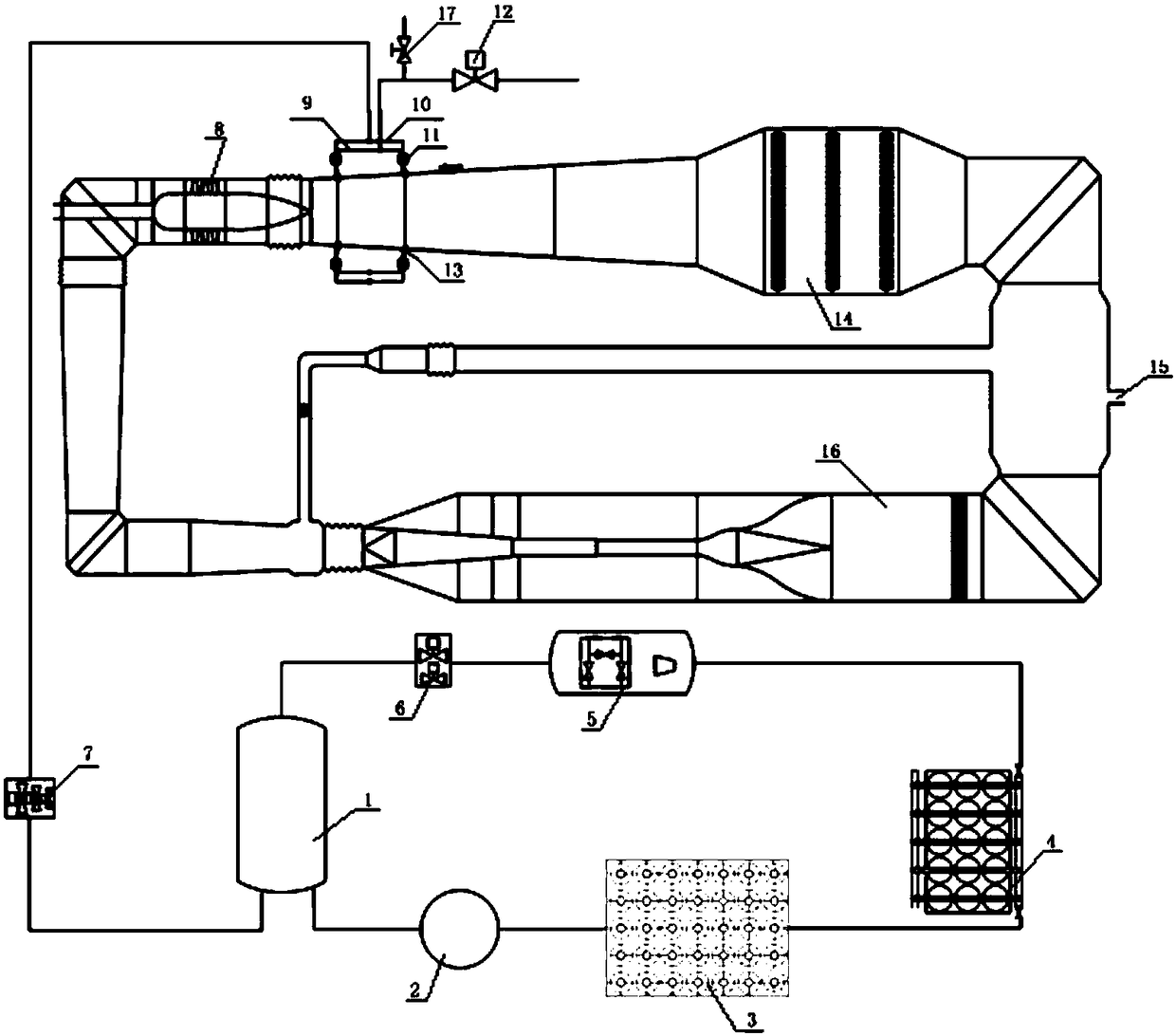
[0101] This embodiment is a safety interlocking method for a continuous wind tunnel cooling system. In order to express clearly, the general structure of the continuous wind tunnel equipped with cooling system is briefly introduced first, and the figure 1 As an example, the liquid nitrogen storage tank 1 in the figure is used for the storage of liquid nitrogen; the liquid nitrogen pump 2 and the vaporizer 3 are used to convert liquid nitrogen into gas nitrogen and store it in the gas cylinder group 4, as a means of pushing liquid nitrogen The driving gas source and the driving gas source of the air control valve; the gas source of the gas cylinder group is adjusted to the required driving gas through the gas distribution table 5; the pushing valve group 6 is placed in the gas distribution table to provide the driving required for squeezing liquid nitrogen gas; the liquid supply valve group 7 is installed in the liquid nitrogen delivery pipeline at the outlet of the liquid nitr...


PUM


Abstract

The invention relates to a safety interlocking method of a continuous wind tunnel cooling system. A cooling control system analyzes a signal which needs monitoring, a safety risk of a wind tunnel andequipment is determined according to the signal, and safety interlocking protection is carried out on the wind tunnel and equipment. Safety interlocking content is comprehensive, reasonable and effectively, basis is provided for normal operation of the continuous wind tunnel cooling system and safety of the wind tunnel and equipment, danger of an abnormity signal is clear, the risk coefficient andsystem risk are determined according to signal values, the danger is quantified, an operator can know the danger of a present fault visually, basis is provided for control decision, and the wind tunnel runs more safely.

Description

technical field [0001] The invention belongs to the field of wind tunnel operation safety protection, in particular to a safety interlocking method for a continuous wind tunnel cooling system. Background technique [0002] The continuous wind tunnel uses a compressor to provide the power source to establish the required Mach number. According to the operating temperature range, the continuous wind tunnel can be divided into conventional wind tunnel, cooling wind tunnel and low temperature wind tunnel. The cooling temperature in the cooling wind tunnel is below zero during the cooling operation. The cooling operation is only one of the multiple operating conditions of the wind tunnel. It is generally realized by configuring the cooling system and injecting liquid nitrogen / liquid ammonia and other refrigerants into the wind tunnel. , using its latent heat of vaporization to realize the cooling operation of the wind tunnel. Taking liquid nitrogen spraying as an example, the co...

Claims


Application Information

Patent Timeline
IPC IPC(8): G01M9/04G01M9/06
Inventor 陈旦张永双周廷波张国彪高超郗忠祥何显中张正科胡旭
Owner NORTHWESTERN POLYTECHNICAL UNIV
Why Eureka
Try Eureka