Quartz vibrating beam accelerometer with self-checking function and manufacturing method and self-checking method thereof

An accelerometer and vibrating beam technology, which is applied in the field of chip bonding and quartz vibrating beam accelerometers, can solve the problems of high contact surface smoothness and flatness, high temperature control requirements, and low long-term stability. The effect of reducing requirements, low process compatibility requirements, and improving reliability

Active Publication Date: 2018-06-12
SOUTHEAST UNIV
View PDF5 Cites 0 Cited by
  • Summary
  • Abstract
  • Description
  • Claims
  • Application Information

AI Technical Summary

Problems solved by technology

Direct bonding is produced by the van der Waals force that attracts each other between molecules, and has high requirements for the smoothness and flatness of the contact surface; anodic bonding does not have high requirements for the bonding interface, but the rate is slow, and voids are prone to appear. High temperature and high pressure processing conditions, and there may be electrical signal interference; the advantages of adhesive bonding are low bonding temperature, low cost, simple process, etc. Commonly used adhesives are organic adhesives, which have low long-term stability The disadvantages; eutectic bonding utilizes the characteristics of low melting temperature of some alloys, and uses it as an intermediate medium layer to heat and melt to form eutectic bonding, but generally needs to be carried out in a vacuum or inert gas environment, and requires temperature control higher

Method used


Image

  • Quartz vibrating beam accelerometer with self-checking function and manufacturing method and self-checking method thereof
  • Quartz vibrating beam accelerometer with self-checking function and manufacturing method and self-checking method thereof
  • Quartz vibrating beam accelerometer with self-checking function and manufacturing method and self-checking method thereof

Examples


Embodiment Construction

[0023] The present invention will be further described below in conjunction with the accompanying drawings.

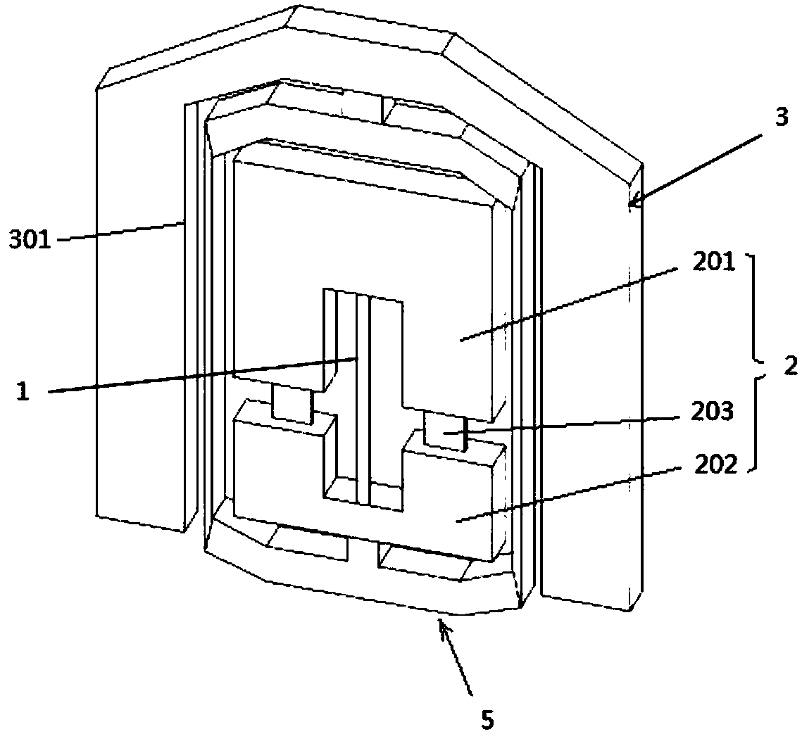
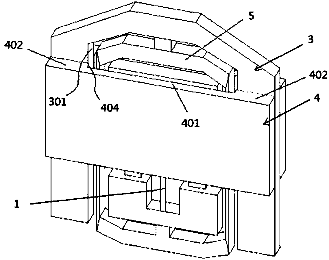
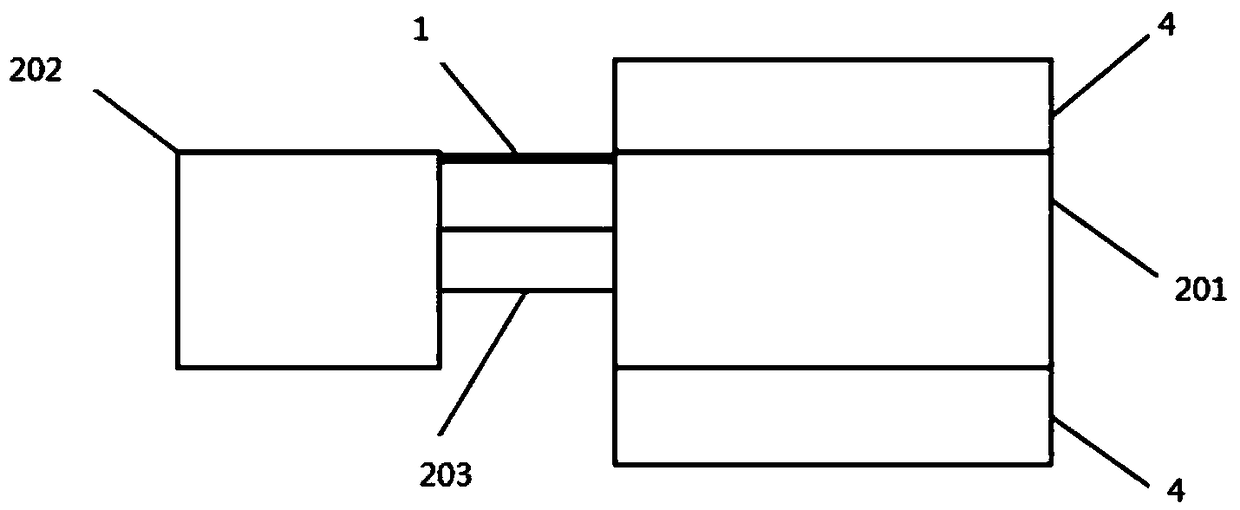
[0024] Such as figure 2 As shown, the quartz beam accelerometer of the present invention includes a quartz beam accelerometer module and a self-check module. The quartz vibrating beam accelerometer module includes a quartz vibrating beam 1 and a quality-flexible structure 2, both of which can be integrated or split, wherein the quality-flexible structure 2 includes a movably connected mass 201 and a base 202, preferably Yes, the mass block 201 and the base 202 are connected by a flexible hinge 203 . In the present invention, the quartz vibrating beam 1 and the mass flexible structure 2 can be but not limited to be arranged in the isolation frame 5 , specifically the base 202 is connected to the isolation frame 5 , and the isolation frame 5 is connected to the installation frame 3 . The self-inspection module is passed above and / or below the mass block 201 (in this p...


PUM


Abstract

The invention discloses a quartz vibrating beam accelerometer with a self-checking function and a manufacturing method and self-checking method thereof. The accelerometer comprises a quartz vibratingbeam, a mass-flexible structure and a mounting frame, wherein the mass-flexible structure comprises a mass block and a base which are movably connected, a polar plate is arranged on the upper portionand/or lower portion of the mass block, the two ends of the polar plate are connected with the mounting frame, and there is a space between the middle of the polar plate and the mass block. At the same time, the surfaces, opposite to each other, of the middle of the polar plate and the mass block are provided with conductive films respectively. According to the accelerometer, the self-checking function is added, the defects and faults of the accelerometer can be detected in time, and correspondingly the reliability of the quartz vibrating beam accelerometer is greatly improved. Meanwhile, thequartz vibrating beam accelerometer has the advantages that the manufacturing process is incomparable in the aspects of cost, size, power consumption, precision and the like and can be widely used inthe fields of high precision inertial navigation and military projects.

Description

technical field [0001] The present invention relates to a quartz vibrating beam accelerometer and a manufacturing method thereof, in particular to a quartz vibrating beam accelerometer with a self-checking function, and to a chip bonding method that requires precise mechanical positioning while realizing electrical connection, and the The accelerometer's self-test method. Background technique [0002] With the rapid development of sensor technology and microelectronics technology, MEMS sensors are constantly innovating and developing. The volume of MEMS sensors is getting smaller and smaller, the structure is more and more complex, the precision is constantly improving, and the requirements for reliability are getting higher and higher, which requires higher precision and more stable processing technology to protect it. [0003] Quartz vibrating beam accelerometer is an acceleration sensor based on the force-frequency effect of the vibrating beam resonator and the piezoelec...

Claims


Application Information

Patent Timeline
Patent Type & Authority Applications(China)
IPC IPC(8): G01P15/08G01P15/09G01P15/097
CPCG01P15/08G01P15/09G01P15/097G01P2015/0868
Inventor 梁金星赵奚
Owner SOUTHEAST UNIV
Why Eureka
Try Eureka