
Device and method for determining currents of electrolytic cell cathode plate

A technology for determining devices and electrolyzers, applied to measuring devices, measuring only current, measuring current/voltage, etc., can solve the problem of large current error of the cathode plate and achieve the effect of reducing measurement error and improving accuracy

Inactive Publication Date: 2018-06-12
NORTH CHINA UNIVERSITY OF TECHNOLOGY
View PDF2 Cites 2 Cited by
  • Summary
  • Abstract
  • Description
  • Claims
  • Application Information

AI Technical Summary

Problems solved by technology

Although the total current on the electrolytic cell can be detected and controlled online through the rectifier unit, there has been no corresponding determination method for the current passing through each cathode plate or anode plate on the electrolytic cell. According to the number of cathode plates, the current on the cathode plate is divided equally to estimate the current carried by the cathode plate, but the current error of the cathode plate determined by the above method is extremely large

Method used


Image

  • Device and method for determining currents of electrolytic cell cathode plate
  • Device and method for determining currents of electrolytic cell cathode plate
  • Device and method for determining currents of electrolytic cell cathode plate

Examples


specific Embodiment approach 1

[0046] Specific implementation mode one: measurement of cathode current in copper electrolytic refining

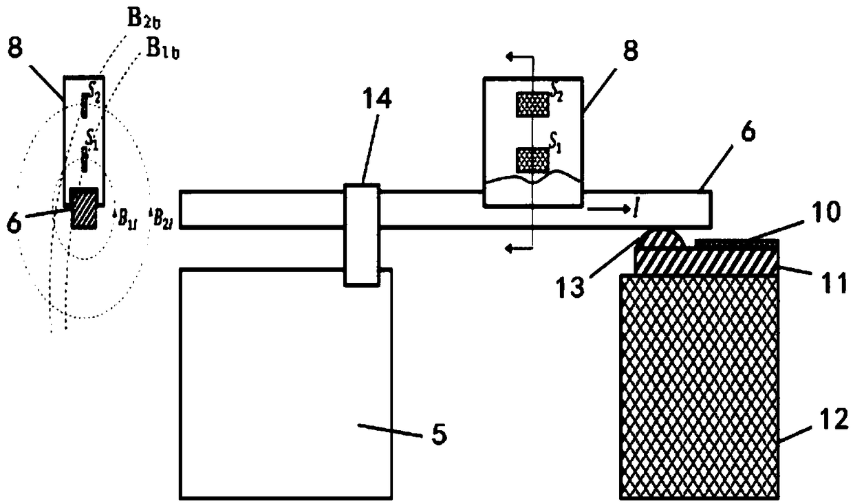
[0047] Such as figure 2 As shown, the measurement box 8 is a measurement box 8 with two Hall elements built in. A concave groove with a surplus width of 30 mm is processed at the bottom of the measurement box 8, and the Hall elements S1 and S2 for measuring the magnetic field are respectively fixed at a height of 10 mm and 30 mm from the bottom surface of the groove, and the working surfaces of the Hall elements S1 and S2 are parallel to the second The center line of the conductive rod 6 ensures that the magnetic field lines of the magnetic field generated by the current of the second conductive rod 6 pass through the working surfaces of the Hall elements S1 and S2 vertically. Use a controllable current power supply to determine the calibration constant k on a conductive rod with the same conductive structure layout. Clamp the measuring box 8 in the middle of the second...

specific Embodiment approach 2

[0049] Specific implementation mode two: measurement of nickel electrolysis cathode current

[0050] Such as figure 2 As shown, the measurement box 8 is a measurement box 8 with two Hall elements built in. A circular concave groove with a diameter of 20 mm is machined at the bottom of the measurement box 8, and the Hall elements S1 and S2 for measuring the magnetic field are respectively fixed at a height of 10 mm and 30 mm from the bottom surface of the groove, and the working surfaces of the Hall elements S1 and S2 are parallel to The center line of the second conductive rod 6 ensures that the magnetic field lines of the magnetic field generated by the current of the second conductive rod 6 pass through the working surfaces of the Hall elements S1 and S2 vertically. Use a controllable current power supply to determine the calibration constant k on a conductive rod with the same conductive structure layout. Clamp the measuring box 8 in the middle of the second conductive r...

specific Embodiment approach 3

[0051] Specific implementation mode three: measurement of zinc electrolysis cathode current

[0052] Such as figure 2 As shown, the measurement box 8 is a measurement box 8 with two Hall elements built in. A rectangular concave groove with a diameter of 20 mm is machined at the bottom of the measuring box 8, and the Hall elements S1 and S2 for measuring the magnetic field are respectively fixed at a height of 10 mm and 30 mm from the bottom surface of the groove, and the working surfaces of the Hall elements S1 and S2 are parallel to the first The center line of the two conductive rods 6 ensures that the magnetic field lines generated by the current of the second conductive rod 6 pass through the working surfaces of the Hall elements S1 and S2 vertically. Use a controllable current power supply to determine the calibration constant k on a conductive rod with the same conductive structure layout. Clamp the measuring box 8 in the middle of the second conductive rod 6, the dis...


PUM


Abstract

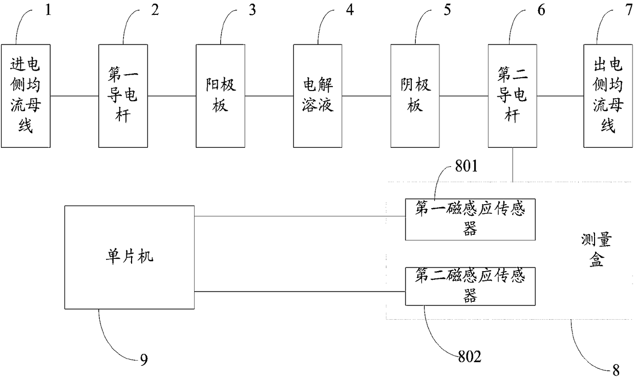
The invention discloses a device and method for determining the currents of an electrolytic cell cathode plate. The device is arranged on a to-be-detected electrolytic cell. The to-be-detected electrolytic cell comprises a plurality of serial-connection structures which are parallelly arranged. Each serial-connection structure comprises current-entering-side current-sharing bus, a first conductiverod, an anode plate, an electrolytic solution, a cathode plate, a second conductive rod and current-discharge-side current-sharing bus which are sequentially connected. The device corresponds to eachserial-connection structure. The device comprises a measuring box and a single-chip microcomputer, wherein a plurality of magnetic induction sensors are arranged in the measuring box, and the single-chip microcomputer is connected with the magnetic induction sensors; the working faces of the magnetic induction sensors are located on the same plane, and the plant is vertical to the upper surface of the second conductive rod and the magnetic lines of a magnetic field generated by currents on the second conductive rod. By the device or method, the measuring accuracy of the currents of one optional cathode plate in the electrolytic cell can be increased, and measuring errors can be reduced.

Description

technical field [0001] The invention relates to the technical field of current measurement, in particular to a device and method for determining the cathode plate current of an electrolytic cell based on an aqueous solution. Background technique [0002] The electrolytic cell used for aqueous electrorefining and electrolytic deposition of metals such as copper, lead, zinc, nickel, etc. generally includes dozens of anode plates and a corresponding number of cathode plates, and the anode plates and cathode plates are arranged crosswise and side by side. The current on the cathode plate, that is, the current density on the surface of the cathode plate, is directly related to the key production indicators such as the current efficiency of the cathode plate, the quality of the product on the cathode plate, and the energy consumption of the product. Usually, the above-mentioned optimal index can be obtained only when the current density is within a reasonable range, that is, the c...

Claims


Application Information

Patent Timeline
Patent Type & Authority Applications(China)
IPC IPC(8): G01R19/00C25C7/00
CPCG01R19/0092C25C7/00
Inventor 赵仁涛铁军张志芳郑文堂范洪涛
Owner NORTH CHINA UNIVERSITY OF TECHNOLOGY
Learn More